Then some of us were doing this not just to keep a stable FFT bin but to allow looking at 1/F offset noise. You know critical band issues.
ES
We are looking at THD at the moment, only.
In a way this is what degeneration does. If we can use a none linear element where our de-gen resistor goes it might work.
could get 2h down but noise up. What about 3H?
The two topologies have also been described as compressive and expansive. Together they are more linear than either, alone.
Or, one is predistorted for the other. Who has already done this for audio or oscillators? certainly there are such circuits to apply here?
maybe? If not what can we configure?
Thx-RNMarsh
Last edited:
Predistortion works to a degree. The ST1000 uses it to get low distortion from the varactor modulator. You can get below .05% THD but the tweaking is not easy. However you are looking for matching a nonlinearity 60-80 dB lower than that. I'm not sure how to do something like that. It seems easier in the frequency domain.
The point is the lightbulb oscillator does have two loops a thermal loop (very slow) and the compressive non-lineartiy. His point is that if you defeat the later by making it too good the amplitude "squeegs". Jim Williams thought his work applied directly to the LTC oscillator which does have level detector, etc., the S&H and other sophisticated AGC aides might change the game (I don't know).
I don't think it applies to linear leveling loops. With an ideal peak detector/multiplier, 1st order settling could be done in 1.5 cycles with zero distortion contribution. That's IIRC what Meyer-Ebrecht wrote in "Schnelle Amplitudenregelung harmonischer Oszillatoren" on this.
Predistortion works to a degree. The ST1000 uses it to get low distortion from the varactor modulator. You can get below .05% THD but the tweaking is not easy. However you are looking for matching a nonlinearity 60-80 dB lower than that. I'm not sure how to do something like that.
Fully agree--distortion cancellation needs a dependable and simple to model (e.g. independent from or at least directly/inversely proportional to frequency) distortion source. The after "good contemporary design practice" remaining distortion sources are anything but this--complex in nature, and sometimes with large spread from specimen to specimen.
Samuel
Samuel, I guess I'll let that point rest for now. I might play with some sims sometime to convince myself.
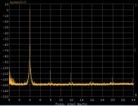
Here's part 1 of my Wein bridge as untra-high Q amplifier experiment. I rearranged my light bulb oscillator to make it an oscillator with "tickler". I took the most horrible function generator I had (HP3311A) diode shaping and massive jitter. and tweaked the oscillator to just below oscillation and injected the HP via a 2Meg resistor. I could stablilize it at 20V p-p and take measurements. There was one very unexpected and interesting result. Apparently since the Wein network has an abrupt phase transition a lot of the jitter is converted to AM, my guess since this was visually very apparent. The spectral results were OTOH quite dramatic.
EDIT - PIM detector!?
Attachments
Last edited:
Samuel, I guess I'll let that point rest for now. I might play with some sims sometime to convince myself.
Here's part 1 of my Wein bridge as untra-high Q amplifier experiment. I rearranged my light bulb oscillator to make it an oscillator with "tickler". I took the most horrible function generator I had (HP3311A) diode shaping and massive jitter. and tweaked the oscillator to just below oscillation and injected the HP via a 2Meg resistor. I could stablilize it at 20V p-p and take measurements. There was one very unexpected and interesting result. Apparently since the Wein network has an abrupt phase transition a lot of the jitter is converted to AM, my guess since this was visually very apparent. The spectral results were OTOH quite dramatic.
EDIT - PIM detector!?
"OTOH" ??? Don't know this one.
Samuel, I guess I'll let that point rest for now. I might play with some sims sometime to convince myself.
Here's part 1 of my Wein bridge as untra-high Q amplifier experiment. I rearranged my light bulb oscillator to make it an oscillator with "tickler". I took the most horrible function generator I had (HP3311A) diode shaping and massive jitter. and tweaked the oscillator to just below oscillation and injected the HP via a 2Meg resistor. I could stablilize it at 20V p-p and take measurements. There was one very unexpected and interesting result. Apparently since the Wein network has an abrupt phase transition a lot of the jitter is converted to AM, my guess since this was visually very apparent. The spectral results were OTOH quite dramatic.
EDIT - PIM detector!?
Why do you need the light bulb? Why one stage of wein filter? And what do you get driving it with a decent oscillator?
(Really Cool!)
Last edited:
Why do you need the light bulb? Why one stage of wein filter? And what do you get driving it with a decent oscillator?
(Really Cool!)
The light bulb was removed and I made the feedback network with 1k Ohm - 50 Ohm pot - 500 Ohm. The pot acts like the tickler in a regen radio, it is tuned to just below oscillation.
Further experiments follow.
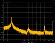
Dave this is an experiment I thought of last week after playing with the injection lock. Skip the oscillation and AGC but make an ultra-high Q amplifier. From the pics you can see huge harmonic attenuation. Oh, do you mean OTOH = on the other hand ?
I'm going to try this to detect the primary Schuman resonance (~7.5Hz) with only a whip antenna.
Last edited:
That would be a good test of a selective amplifier.
What's the difference between a selective amplifier and a high Q bandpass filter?
How high was the Q ? Can you put a number on it?
To what extent would other means to get high Q result in similar increases in AM?
How can you tell it isnt from noise/jitter at/near the Fo?
-RNM
There is such a circuit as a Q multiplier used with lower Q bandpass filters to increase the Q. But it one more amplifier.
How high was the Q ? Can you put a number on it?
To what extent would other means to get high Q result in similar increases in AM?
How can you tell it isnt from noise/jitter at/near the Fo?
-RNM
The short version? Do all high Q BP filters do this...? create AM distortion.
If the answere is No... then what caused it in your method/circuit?
PS---> I will have an AP-7722A here next week to look at. Its osc spec is less than .0002%.
I'll comapre the schematic of the VP-7723A (.0005%) to it to see how or what they did to get thd reduced.
-RNM
Last edited:
Dick,
All high Q filters create amplitude variation if the input frequency wiggles around.
The Q as defined by the 3 db bandwidth in hertz divided by the center frequency is very high but not really shown in his plot.
The example he showed is .00065% distortion. (By eyeball) If he used a clean stable oscillator he would easily be an order of magnitude better.
ES
Had some ground loop problems tonight but I just got an EMU 0204 and it seems to work fine doing simultaneous input and output. I set up tonight initially with two computers and two USB sound cards (a grounding mess). The short of it is that everything looks fine, with a sound card generated sine wave it is very stable and the THD looks to be amplifier limited. I let it run for 5 hours and the amplitude was very stable.
To properly determine if the close in noise is am or fm you need to compare the upper and lower sidebands. If they are in phase its amplitude, out of phase is frequency. And I don't have a clue as to how you would actually measure this, especially for random noise.
You could measure Allen deviation to test for frequency stability but that is long term stuff and probably not audible in any sense. Injection locking would make a big improvement but do nothing useful for actual distortion and possibly will make the noise higher. The output will have noise contributions from both sources.
You could measure Allen deviation to test for frequency stability but that is long term stuff and probably not audible in any sense. Injection locking would make a big improvement but do nothing useful for actual distortion and possibly will make the noise higher. The output will have noise contributions from both sources.
It's a very interesting means to generate a freq. Can you get lower thd from it? .00065% is very good, of course. But not better than stock K-H or Panansonic or tweaked HP 339A etc. But nice concept which i really appreciate learning about its working. How low distortion can you get out of it? More than -120? More than -130? It needs to be at least -130 to be reasonably competitive. Can it be better than Victor's?
-RNM
-RNM
Last edited:
Had some ground loop problems tonight but I just got an EMU 0204 and it seems to work fine doing simultaneous input and output. I set up tonight initially with two computers and two USB sound cards (a grounding mess). The short of it is that everything looks fine, with a sound card generated sine wave it is very stable and the THD looks to be amplifier limited. I let it run for 5 hours and the amplitude was very stable.
If you are not already below your noise floor, then you can add an RC filter on the output and raise the noise and get 6 db less 2nd.
Of course you can parallel Wein filters, but I suspect with the quality of parts available you are at or below measurable distortion.
Scott I think using the sound card as the source is a nice improvement. Now all you have to do is make it a tracking filter. Instead of trying to build a leveler a tracker can have the knowledge of the target frequency. So using D/As for both the R and C would allow that. Relay switch R 2R or C 2C networks with good layout are the best method of doing that as far as I know.
So it should be possible to build a worlds best oscillator for fixed frequencies at modest cost.
So now you can claim -200 db as there is no way to measure it!
Keep on truckin'
ES
Last edited:
- Home
- Design & Build
- Equipment & Tools
- Low-distortion Audio-range Oscillator