Anecdotally -- and why not? -- I was working on my version of the HP 339A osc. and was slowly adjusting the feedback pot, while watching distortion using my T-T filter, the EMU 0204 and ARTA. I also was eyeing output level, and the gate voltage on the JFET -- it helps to have four eyes.
The oscillator was running at 6.3VRMS into a 10k load at 1kHz, and the gate voltage was about -0.4VDC. As I made a tiny tweak, I noticed that the distortion products were dropping slowly into the noise, while the output didn't change level. The FET basically squashed, and somehow the oscillator was in metastable equilibrium, with ZERO distortion above the -145dBV noise floor -- that lasted about 5 seconds, while I picked my jaw up off the floor. Then the distortion products came roaring back.
Both David and Demian have made the point that AGC is the source of oscillator distortion after everything else has been fixed, and I know first-hand that this is so. I am so hugely waiting for David to finish his SVO....
Anecdotally -- and why not? -- I was working on my version of the HP 339A osc. and was slowly adjusting the feedback pot, while watching distortion using my T-T filter, the EMU 0204 and ARTA. I also was eyeing output level, and the gate voltage on the JFET -- it helps to have four eyes.
The oscillator was running at 6.3VRMS into a 10k load at 1kHz, and the gate voltage was about -0.4VDC. As I made a tiny tweak, I noticed that the distortion products were dropping slowly into the noise, while the output didn't change level. The FET basically squashed, and somehow the oscillator was in metastable equilibrium, with ZERO distortion above the -145dBV noise floor -- that lasted about 5 seconds, while I picked my jaw up off the floor. Then the distortion products came roaring back.
Both David and Demian have made the point that AGC is the source of oscillator distortion after everything else has been fixed, and I know first-hand that this is so. I am so hugely waiting for David to finish his SVO....
This is exactly right. It usually comes down to AGC in one way or another if really good op amps are used. For the AGC, it is either ripple in the AGC control signal or distortion in the AGC element itself, like the JFET.
There are many different ways of minimizing the impact of AGC control voltage ripple, and there is usually a tradeoff with settling time. More sophisticated signal level detection, such as multiphase rectification and sample-holds, is one of them. Heavier AGC filtering lengthens settling time and reduces stability of the AGC control loop. A low AGC loop gain also reduces distortion from the AGC ripple, but also can lengthen settling time and may limit the available AGC correction range. Greater precision in the frequency-setting elements can sometimes reduce the needed AGC control range. Greater AGC control range can be needed at higher frequencies where limited gain-bandwidth product in the SV oscillator op amps begins to have influence.
The use of an AGC loop speed-up circuit that comes into play when the AGC error is large can be very helpful in breaking some of these relationships. In the oscillator I used in the SV oscillator in my distortion analyzer, a pair of back-to-back diodes across part of the AGC integrator resistor helped greatly in achieving good settling time and adequate AGC range while keeping AGC loop gain low in the quiescent state. The schematic for that oscillator and the THD analyzer is on my website at CordellAudio.com - Home.
Achieving extremely low distortion with decent settling times at very low frequencies, such as 20Hz, is an especially difficult test for oscillators insofar as AGC ripple influence is concerned.
The distortion contribution of the JFET AGC element can be minimized by keeping the signal across it small and by using a JFET with a high pinchoff voltage. However, keeping the signal across the JFET small while retaining adequate AGC control range will usually increase oscillator noise. Optimizing the amount of gate feedback (nominally 50%) can make a big improvement in the distortion introduced by the AGC JFET. Using low-noise design techniques in the AGC control element circuit can help here.
Cheers,
Bob
When I switched to an osc. AGC system which didnt use a jFET for control element, the distortion dropped by 50%.
However, the THD residual is still from the osc itself.... which when changing its opamp and control opamp, the distortion is now 20dB lower! Add another zero.
Now it seems again to be limited to oscillator circuit and noise floor. The jFET controlled oscillators cannot get lower than KroneHite later models which do not use jFEt as control element.
Thx-RNMarsh
Last edited:
BTW --- Scott Wurcer designed an oscillator which had distortion of 0.1ppm !
havent seen the schematic though.
Thx-RNMarsh
It used SSM VCA for control.
BTW -- my SYS One Audio-Precision - dual domain - it DOES use an ADC/DAC and it is 16 bits !! That explains the higher than expected thd on the dut being limited to mid 90 dB's when using FFT system.... while swept sine oscillator was lower THD. Now I know nothing was wrong with it and now I'll have to go get it back --- in Bangkok. [ I can use the oscillator portion and swept sine data... maybe lower the osc thd, too.]
Thx-RNMarsh
Thx-RNMarsh
Last edited:
The FET basically squashed, and somehow the oscillator was in metastable equilibrium, with ZERO distortion above the -145dBV noise floor -- that lasted about 5 seconds, while I picked my jaw up off the floor. Then the distortion products came roaring back.
I have observed that with other AGC's, like balancing a pencil on its end.
I must say that I did not read the whole thread since I'm more
interested in noise than distortion (for non-audio reasons)
but -
If we can build a SV oscillator that nearly achieves nirvana,
we should be able to build an even better SV filter that is
not sandbagged with AGC problems.
A few frequencies should be enough??
regards, Gerhard
interested in noise than distortion (for non-audio reasons)
but -
If we can build a SV oscillator that nearly achieves nirvana,
we should be able to build an even better SV filter that is
not sandbagged with AGC problems.
A few frequencies should be enough??
regards, Gerhard
BTW -- my SYS One Audio-Precision - dual domain - it DOES use an ADC/DAC and it is 16 bits !! That explains the higher than expected thd on the dut being limited to mid 90 dB's when using FFT system.... while swept sine oscillator was lower THD. Now I know nothing was wrong with it and now I'll have to go get it back --- in Bangkok.
Scott and me already told you this a dozen pages back. You're simply not using this excellent audio analyzer correctly. You need to route the ADC *after* the notch filter, and the 16 bits will *not* limit the THD you're measuring (8 bits would probably be enough to digitize a notch filter residual). I've given you the details about the correct settings, if you can't figure this out from these notes either RTFM or at least post a screenshot about the current settings you're using so we can point you in the right direction. But please stop blaiming AP, thanks!
Samuel
3H gone
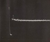
Still working with existing products.... the KH 4402B in this case and as with the HP 339A, some trim pots need replacing which are in the signal path. This time it is in the control feedback opamp AVC (AGC) gain control. R145 (1K) which was a ten turn. Now it is replaced with a 28 turn and better contacts or what-ever and the 3H is just about dropped into the noise. THD+N is a tick under .00004% at 1Khz at 7v rms direct out port.
If I cant drop the 2H into the noise, I only have one harmonic to apply a notch filter to it.
Thx-RNMarsh
Attachments
Last edited:
8 bits would probably be enough to digitize a notch filter residual
Samuel
On the AP system 1 at Monster we use to test Richard's amps we have an old 8 bit Picoscope tied to the monitor out (no fft in the box) and it works great. The Picoscope also has much wider bandwidth than the internal FFT would (100 MHz) not that there is much to see past 100 KHz. I'll show him the next time he is at Monster.
Hi Demian,
Your note reminded me that I did try an FFT that is an option on my TEK scope.... it is so weird to use that I gave up on it and pressed the old analog HP analyzer into service and take pictures with a TEK camera.... on old but still usable Polaroid flat pack film type 667. Boy if that isnt a flash back or what! But FFT stuff can be a pain if it isnt worked out well and I dont seem to have the patience needed. Waiting to get the QA400 back up and running. Or maybe a PICO-Scope.
I'll check in with you soon at Monsterland.
Thx-RNMarsh
Last edited:
i do not need a low distorsion generator.?
may this header is provocing a lot and that is what i want !
when i measure an amp ,i want to have an input signal with some distorsion,1,2,3,4,5 etc harmonics and then I like to see the same harmoniclevels in the output.
i think that when we put in zero distorsion and the output shows zero distorsion that that is something different????
When I switched to an osc. AGC system which didnt use a jFET for control element, the distortion dropped by 50%.
However, the THD residual is still from the osc itself.... which when changing its opamp and control opamp, the distortion is now 20dB lower! Add another zero.
Now it seems again to be limited to oscillator circuit and noise floor. The jFET controlled oscillators cannot get lower than KroneHite later models which do not use jFEt as control element.
Thx-RNMarsh
I may have missed something, but what AGC element did you switch to instead of the JFET?
Cheers,
Bob
I must say that I did not read the whole thread since I'm more
interested in noise than distortion (for non-audio reasons)
but -
If we can build a SV oscillator that nearly achieves nirvana,
we should be able to build an even better SV filter that is
not sandbagged with AGC problems.
A few frequencies should be enough??
regards, Gerhard
Good point. Indeed, it could be interesting, at least for investigative purposes, to put such a manual-tuned SV BPF after an SV oscillator and see how much distortion then results.
Cheers,
Bob
A low pass should be even more interesting than a BPF.
BPFs often deliver the difference of two large signals,
and the higher the Q, the larger the filter-internal
signals get. That is not wanted from a dynamic range pov.
A low-Q lowpass is still good for -6dB or so at 2*f per pole
and without resonances.
Gerhard
BPFs often deliver the difference of two large signals,
and the higher the Q, the larger the filter-internal
signals get. That is not wanted from a dynamic range pov.
A low-Q lowpass is still good for -6dB or so at 2*f per pole
and without resonances.
Gerhard
I must say that I did not read the whole thread since I'm more
interested in noise than distortion (for non-audio reasons)
but -
If we can build a SV oscillator that nearly achieves nirvana,
we should be able to build an even better SV filter that is
not sandbagged with AGC problems.
A few frequencies should be enough??
regards, Gerhard
There was a group buy on Glen's SVO, which is described here:
An Audio T.H.D. Analyser
He posted the group buy here:
Who would like an ultra-low distortion audio oscillator PCB? - Page 1
But, all the boards are gone now, as far as I know. The first link has the Gerber files if you want to make your own board.
I posted about the Glen's group buy here:
http://www.diyaudio.com/forums/group-buys/221670-sv-oscillator-pcb-group-buy.html
Mine is up and running now and seems to be great though I have not tested it yet in detail.
A low pass should be even more interesting than a BPF.
BPFs often deliver the difference of two large signals,
and the higher the Q, the larger the filter-internal
signals get. That is not wanted from a dynamic range pov.
A low-Q lowpass is still good for -6dB or so at 2*f per pole
and without resonances.
Gerhard
Not sure I agree with your observation of the BPF, at least insofar as the SV BPF. Note that the SV oscillators are effectively a BPF with a carefully-controlled Q of infinity (that's why they oscillate). The agc controls the damping of this BPF. If the agc reduces the Q a little bit to a finite value, we have a high-Q BPF, but with most of the circulating signal levels about the same if a small input signal at fo is introduced at a low enough level to take the effective pass-band gain into account. I don't think there is a subtraction of two large signals going on there.
Cheers,
Bob
Catch-up summary -
It might be good to recap for late comers who werent following the HP339A saga of mods and upgrades -->
I had an headphone amp I wanted to measure the THD and the SYS 1 A-P FFT showed the thd was higher than I thought it really was. Turned out I was right and the A-P didnt go low enough [A SYS2 does but I dont want to spend that much money just for my curiousity].
I bought an 339A to modify to see if I could measure the THD+n from it. It uses an jFET AGC also. Davada and I got much lower levels from that exercise -both from the analyzer and the oscillator. Then we began looking at the residual with FFT from others -- like Davada had been doing with QA400 unit. That lead to more spin-offs.
I then bought a KH4400 and couldnt get its thd lower than the 339A. And, it also used a jFEt for control in AGC. Then I picked up a ShibaSoku AD725D on eBay and was able to see the individual harmonics again to very low levels. I could directly read Viktors oscillator THD (+N). So back to tuning on oscillators because I wanted more flexibility from my generator source than I could get from Viktor.
I picked up a newer KH 4402B which uses a different type of AGC (without jFET). You can see it from KH schematics from their web site.
I have modified it from what I had found did the greatest good on the other oscillator models... started with the oscillator IC itself. Now I am 20 dB better than stock.
Thats where I am now... I have the instruments to test and the sources to test extreamly high quality circuits and parts/components, now.... quickly and with accuracy.
Several spin-off have occured along the way -- new oscillator designs with new controls and add-on interfaces for ADC/FFT -- davada and demian and others have taken that role on themselves.
My thinking now is there needs to be a fundamentally new way to generate test tones..... my vision is to have a circuit that does harmonic cancellation rather than making them ever more ultra pure in the first place. Something low in harmonics to begin with but relies on a harmonic cancellation technique to derive zero harmonics at the output. Perhaps an inverted derivitive and then summing the results for cancellation. All regulated and normalized for consistant performance.
Thx-RNMarsh
Last edited:
- Home
- Design & Build
- Equipment & Tools
- Low-distortion Audio-range Oscillator