Another issue is that of resultion. I think that quantization noise would introduce significant sidebands/amplitude modulation. A rough calculation lead me to believe that > 16 bit would be required to keep quantization noise below the inherent amplitude noise of a (very) well designed SV oscillator. That's of course again a function of the multiplier decoupling/required settling time. The above number is based on < 10 s to 0.1% for a 100 Hz to 10 Hz range change and a multiplier authority similar to what's found in the AP System One. But that's all plain theory at the moment, I haven't implemented anything.
Samuel
Samuel
If we are talking about the SYS1 then the OSC has four 5534 including the multiplier.
Can't accommodate the two pole comp if going to 1468.
The output amplifier is discrete. It looks more like a power amp.
Is that 6-10dB of disto, noise or both?
Cheers,
Distortion.
The noise is very close to the same depending on exact impedance.
But the 1468 has more open loop gain more bandwidth and more linearity so lower distortion.
On the other hand the OPA 827 is a better choice for high impedance because it is FET input and so lower noise current.
And the AD 797 is best for low impedance.
Last edited:
You can download it here: AP High Performance Audio Analyzer & Audio Test Instruments : Home Starts Page 152. (I should have read it before assuming how the box works.) You need to register first. Its an OK scan of the service manual with all the details. You might have been better off servicing it yourself but you never would have gone down this learning path.
Can you show me the Sys1 oscillator schematic - anyone?
Ill try the opa827 to see what happens compared to others tried.
Thx-RNMarsh
Just for a quick reference.
Attachments
Lowest THD+N at 1-10KHz - for the KH4402B
Ok Thanks both for the schematic info. looks like a lot of 5532/34 opamps which can get upgraded.
Meanwhile, back at the bench -->The KH-4402B has now found an opamp combo that does better than either AD797 or LT1037 or LT1468 alone can do.
Replacing U125 with the AD797 and replacing U141 with the LT1037 now gives the same THD+N level at 1KHz and at 10KHz.
Namely,just under .0001% at .00008-9% at either 1KHz or at 10KHz.
This was done on the X1K scale.... just switching from 1 to 10 on the freq dial. But when using the X100 scale and dialed to 10 (1KHz) the THD+N is even lower -- .00005%")
Before, this combo the THD+N rose at 10KHz. Now it is steady at a low level at 10KHz.
[trim R145 AVC control at 10KHz]
Thx-RNMarsh
Ok Thanks both for the schematic info. looks like a lot of 5532/34 opamps which can get upgraded.
Meanwhile, back at the bench -->The KH-4402B has now found an opamp combo that does better than either AD797 or LT1037 or LT1468 alone can do.
Replacing U125 with the AD797 and replacing U141 with the LT1037 now gives the same THD+N level at 1KHz and at 10KHz.
Namely,just under .0001% at .00008-9% at either 1KHz or at 10KHz.
This was done on the X1K scale.... just switching from 1 to 10 on the freq dial. But when using the X100 scale and dialed to 10 (1KHz) the THD+N is even lower -- .00005%
Before, this combo the THD+N rose at 10KHz. Now it is steady at a low level at 10KHz.
[trim R145 AVC control at 10KHz]
Thx-RNMarsh
Last edited:


Hi Rick,
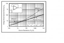
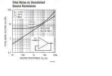
Look for charts like this on the data sheets.
The one for the OPA1641 compares to the ultra low noise OPA1611.
The 1611 doesn't do nearly as well at higher impedance.
The 1468 covers a wide range of input R without the noise curve taking off which makes it ideal for wide range OSC tuning.
It would be pointless to use an OPA1611 or the like above a source R of 1K
Not all data sheets include this chart.
Attachments
Last edited:
Another issue is that of resultion. I think that quantization noise would introduce significant sidebands/amplitude modulation. A rough calculation lead me to believe that > 16 bit would be required to keep quantization noise below the inherent amplitude noise of a (very) well designed SV oscillator. That's of course again a function of the multiplier decoupling/required settling time. The above number is based on < 10 s to 0.1% for a 100 Hz to 10 Hz range change and a multiplier authority similar to what's found in the AP System One. But that's all plain theory at the moment, I haven't implemented anything.
Samuel
This is exactly what is shown... a lot of spurious freqs other than random noise and harmonics of the test signal. It makes it pretty hard to find the DUT harmonic signals/levels from the system's spurious frqs. at low distortion levels.
A serious pcb layout R&D effort will be needed.
Thx-RNMarsh
Hi Rick,
Look for charts like this on the data sheets.
The one for the OPA1641 compares to the ultra low noise OPA1611.
The 1611 doesn't do nearly as well at higher impedance.
The 1468 covers a wide range of input R without the noise curve taking off which makes it ideal for wide range OSC tuning.
It would be pointless to use an OPA1611 or the like above a source R of 1K
Not all data sheets include this chart.
Thats why I want schematics for everything modifyable. To find the R's as well as the opamps being used. The other way is to look at the opamps being used by the mfr and guess from those specs what a subsitute would be.
But if starting from scratch, like you are, then you can tailor everything around your choise. Making DIY creative and unique.
I find that using existing chassis takes a lot of the grounding, shielding, power supply, layout etc already R&D'ed and well thought out. Then its just finding what bad parts or IC upgrades can now do a better job. It cost more money but it takes less time. And, when you are older, the money doesnt matter as much. (If it ever did). I have a lot of things i still want to do and redoing where others have gone and done isnt one of them. But that's just me.
THx-RNMarsh
This is exactly what is shown... a lot of spurious freqs other than random noise and harmonics of the test signal. It makes it pretty hard to find the DUT harmonic signals/levels from the system's spurious frqs. at low distortion levels.
A serious pcb layout R&D effort will be needed.
Thx-RNMarsh
I'm not sure what you are referring to at this stage. If the DAC is generating a sine wave you will have some spuria for a bunch of reasons, if its steering an analog oscillator it can be low pass filtered in ways to prevent it from having an effect.
If we are talking about driving a switched resistor for AGC I think the issue is narrowing the controlled range so that the resistor has a small effect on the output.
For tuning its more complex. The Boonton uses FET's to select the range and a 12 bit DAC to an analog multiplier to do the fine tuning. That part works really well, limited only by the 10 MHz TXCO for accuracy and the phase noise is pretty low for an analog oscillator. I think the analog multipliers are the real limit on the oscillator distortion in the Boonton. They are unadjusted RC4200A's http://www.datasheetcatalog.org/datasheet/fairchild/RC4200.pdf good for 2% linearity.
spuria
Spuria -- is the latin term for she-bastard.
just thought you'd like to get some Jesuitical wisdom out of that.
Spuria -- is the latin term for she-bastard.
just thought you'd like to get some Jesuitical wisdom out of that.
I can use that in many ways. . .
Your thinking details and I am thinking in broader strokes. I'm thinking the implimentation of ADC (and DAC for that matter) varies from brand to brand using same ADC IC. Meaning the spurious freqs are to a large extent due to layout etc.
The goal would be to see nothing but the artifacts of the DUT and random noise. To push those test equipment artifacts below the system noise floor.
Is there a suitable way to turn system test artifacts into noise... randomize them.
Thx-RNMarsh
The goal would be to see nothing but the artifacts of the DUT and random noise. To push those test equipment artifacts below the system noise floor.
Is there a suitable way to turn system test artifacts into noise... randomize them.
Thx-RNMarsh
Your thinking details and I am thinking in broader strokes. I'm thinking the implimentation of ADC (and DAC for that matter) varies from brand to brand using same ADC IC. Meaning the spurious freqs are to a large extent due to layout etc.
The goal would be to see nothing but the artifacts of the DUT and random noise. To push those test equipment artifacts below the system noise floor.
Is there a suitable way to turn system test artifacts into noise... randomize them.
Thx-RNMarsh
Dither.
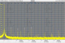
Dither works really well for measurements systems, except when there is deterministic stuff that the dither is not affecting. Here are two measurements that illustrate the issue. Both were made with crystal master clocks. One with the internal oscillator (a gate type oscillator) and the other with an external OXCO connected with clip leads. On the external oscillator (powered from a wall wart) the extraneous stuff is just missing. With the internal oscillator you can see the effects of the counter/divider stages modulating the oscillator. No amount of dither would eliminate the artifacts. Delta Sigma ADC's are supposed to be less sensitive to jitter and may well be but this still highlights that everything is important.
I have a time mark generator I use for testing jitter in ADC's. It has an OXCO as its reference and a synchronous divider. It should be really free of jitter at 1 KHz. However I traced down some 60Hz and 120 Hz sidebands to supply modulation from a less than ideal layout around the oscillator. Cutting the ground plane and returning the primary supply ground a different way reduced the sidebands by 20 dB. These are really subtle details that make a difference when you get below 100 dB.
When you can see this far down the problems never go away, they just move around.
Attachments

Dither works really well for measurements systems, except when there is deterministic stuff that the dither is not affecting. Here are two measurements that illustrate the issue. Both were made with crystal master clocks. One with the internal oscillator (a gate type oscillator) and the other with an external OXCO connected with clip leads. On the external oscillator (powered from a wall wart) the extraneous stuff is just missing. With the internal oscillator you can see the effects of the counter/divider stages modulating the oscillator. No amount of dither would eliminate the artifacts. Delta Sigma ADC's are supposed to be less sensitive to jitter and may well be but this still highlights that everything is important.
I have a time mark generator I use for testing jitter in ADC's. It has an OXCO as its reference and a synchronous divider. It should be really free of jitter at 1 KHz. However I traced down some 60Hz and 120 Hz sidebands to supply modulation from a less than ideal layout around the oscillator. Cutting the ground plane and returning the primary supply ground a different way reduced the sidebands by 20 dB. These are really subtle details that make a difference when you get below 100 dB.
When you can see this far down the problems never go away, they just move around.
How much this is just FFT?
How much this is just FFT?
???
Which?
FFT is the only technique that can get subfractional Hertz bandwidth like this.
layout, grounding, shielding, xtal osc and dither will do a huge amount of improvement as a test instrument. And, a passive (active?) filter on the input to ADC.
What can be done - and how to - along these lines with an existing ADC system? How can they be modified along these lines for improvement?
Thx-RNMarsh
What can be done - and how to - along these lines with an existing ADC system? How can they be modified along these lines for improvement?
Thx-RNMarsh
Last edited:
- Home
- Design & Build
- Equipment & Tools
- Low-distortion Audio-range Oscillator