Note that this is not a general-purpose distortion analyzer; it can just analyze two-ports (in particular passives), and it's just the 3rd harmonic residual which is extremely low (and not e.g. the 2nd). One could imagine adapting this for a normal low distortion oscillator, and making the tuned network switchable between 2nd and 3rd harmonic reduction. But this sounds like a tremendously complicated undertaking...
Samuel
The plots in my AD797 AES preprint were done with only a Sound Tech 1700A and passive L/C post filtering, with passive notching of the fundamental on the output. The L's were air core up on wooden blocks, I could resolve -150dB thirds from a pair of diagonal cutters waved near the L.
Last edited:
The plots in my AD797 AES preprint were done with only a Sound Tech 1700A and passive L/C post filtering, with passive notching of the fundamental on the output. The L's were air core up on wooden blocks, I could resolve -150dB thirds from a pair of diagonal cutters waved near the L.
Cool--what frequency was this (don't have the preprint at hand), and what L values?
I'm answering my first Q myself now that I have the preprint in front of me--20 kHz. Would be interested to see the filter schematic (i.e. order and impedance niveau).
Attached is the description how Baxandall resolved -120 dB in 1978.
From which text is this?
Samuel
For the records some details on the CLT1 Component Linearity Tester:
* http://www.linearaudio.net/images/letters.pdf/volume1ltecb.pdf (on page 2 several links to PDFs describing its application)
* US patent 3493852 (describing the basic implementation of it)
* Canada patent 656622 (describing the basic implementation of it)
Samuel
* http://www.linearaudio.net/images/letters.pdf/volume1ltecb.pdf (on page 2 several links to PDFs describing its application)
* US patent 3493852 (describing the basic implementation of it)
* Canada patent 656622 (describing the basic implementation of it)
Samuel
Last edited:
From which text is this?
Audio Power Amplifier Design, Pt.5 (WW Dec.78, p.56)
@RNMarsh -- the HP 339A has very low distortion to begin with, in the area of -125dB or less @ 1kHz (re full output of 6.3VRMS, loaded only by its own attenuator) for the first two harmonics, and fading quickly for higher order products.
Samuel may be right about an active low-pass filter following the oscillator not adding any significant distortion -- layout and choice of amp and other components will obviously be critical.
For me, for single frequency, I would use an air-core coil and polypropylene or polystyrene caps and do a passive bandpass filter. I thank Patrick Turner, down in Canberra, for demonstrating to me that this is indeed effective. But maybe the opposite direction of the Coriolis effect down under makes the electrons spin in the right direction to eliminate distortion....
For me, for single frequency, I would use an air-core coil and polypropylene or polystyrene caps and do a passive bandpass filter. I thank Patrick Turner, down in Canberra, for demonstrating to me that this is indeed effective. But maybe the opposite direction of the Coriolis effect down under makes the electrons spin in the right direction to eliminate distortion....
What would you set the -3dB (or -6dB) point at for a 1kHz oscillator? 1.5kHz? I guess this is related to the Q of the filter.
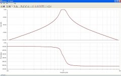
Tune the filter peak to the 1kHz fundamental and let the skirts take care of themselves -- and it does depend on Q. The primary advantage of a bandpass over a lowpass is deeper attenuation at the 2nd H.
What should be the impedance of the filter?
I'm going to need a good sized box to hold all of this stuff!
Attachments
Last edited:
I'm answering my first Q myself now that I have the preprint in front of me--20 kHz. Would be interested to see the filter schematic (i.e. order and impedance niveau).
2nd order 600 Ohms. Don't remember the values. #16 copper magnet wire and the best film caps we had.
Samuel
@dirkwright -- difficult to say -- it majorly depends on the output capabilities of the device doing the driving. In the case of low-distortion oscillators, I would shoot for a high peak Z, but I haven't done a serious LC bandpass filter in years and just don't remember the practical consequences of various issues. There probably are many sites online that can help with basic design parameters and results.
@dirkwright -- difficult to say -- it majorly depends on the output capabilities of the device doing the driving. In the case of low-distortion oscillators, I would shoot for a high peak Z, but I haven't done a serious LC bandpass filter in years and just don't remember the practical consequences of various issues. There probably are many sites online that can help with basic design parameters and results.
Wouldn't the filter determine the effective source impedance for the oscillator/filter combination? I'm not sure what kind of load Victor's oscillator can drive, so I don't have a clue as to what impedance to make the filter. I do know that this online calculator I'm using gives me huge inductors for 10kohms characteristic impedance.
http://www.the12volt.com/caraudio/crosscalc2.asp#cc
So, assuming the oscillator can't drive very much, I'd need a buffer between it and the filter if the filter was low impedance.
Well, a bandpass filter will have relatively hi Z at the peak, where the signal level is also highest, and lower Z in the stop band. So using some series R at the output of the oscillator will be a good idea -- I suggest a couple of kohms just to keep the load on the oscillator light, even in the stop band. The resulting insertion loss shouldn't be high at the fundamental, which is the one and only frequency you want.
OK, thanks. So, if the filter is 600 ohms, then that would be the source impedance for the oscillator/filter combination, and I can insert a couple of kohms between the oscillator and the filter to keep the oscillator happy. Sounds good. I don't have to make or buy monster inductors!
Well, you do have to worry about the loss between the osc, output and the filter input at the filter's peak frequency. I would design the filter for a higher nominal Z, but as I said, it's been awhile since I did any work with passive LC bandpass filters and I just don't remember the Z characteristics at all. Just see what you can find online as far as designs go. It doesn't take much Q to do a really good job -- I'd shoot for anything over 6 but less than 60....
- Home
- Design & Build
- Equipment & Tools
- Low-distortion Audio-range Oscillator