@klewis -- Ken, I would stick with the values you have in the first schematic -- they will do better on noise and stray C will be less of a factor. Can't remember what I said about it on the page, so will have to re-read it....
Dick
OK, back to version one it is. thanks Dick.
Ken
Supply decoupling, I am learning, is a very tricky subject. I always used to just decouple with ceramics or film caps near the IC pins to ground, but it may be better to bypass the two supplies to each with with a cap, and then bypass from one supply to ground -- or not -- this is in very low noise, low distortion applications. I need to spend time playing with decoupling on one of my project oscillators to evaluate, and I'm sure every situation is different. As usual, everything I think I know is wrong...
@richEEM,
When your looking for your decoupling spot, can you solder one end to somthing like a a mini coax then use short clip length on the other lead
to find the best config?
As for me, I'm still in ELE 101, trying to figure out the "right" way
to install a trimmer in my HP339a.
When your looking for your decoupling spot, can you solder one end to somthing like a a mini coax then use short clip length on the other lead
to find the best config?
As for me, I'm still in ELE 101, trying to figure out the "right" way
to install a trimmer in my HP339a.
I regret bringing the bad news. I just learned that Ken Lewis passed away on November 18th. Very sad news. I do not know the details. When and if I find out more I will let you know.
Vlad,
You can find more details, including a link to his obituary, here:
http://www.diyaudio.com/forums/lounge/265761-rip-ken-lewis-klewis.html#post4140725
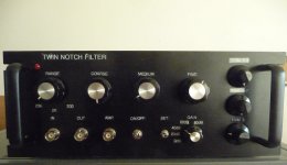
After building the Moore twin notch filter last year I did recently build a second iteration of it. I realized how sensitive the filter was to components when I tried to get a reasonably stable notch deeper than 100dB, so I set the goal to achieve the deepest stable notch possible by modifying the original design and using matched precision components.
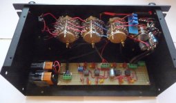
In order to achieve this two things are of utmost importance, use of matching high quality capacitors, resistors and pots. Matching capacitors to 1% isn't good enough when the resistor ladders with 1% tolerance resistors and trim pots can provide a very exact matched resistance. I started out by selecting high quality polystyrene caps from a large batch using an excellent but low cost 7-digit capacitance meter (DIY Kits RH Electronics ) for precise matching. I improved the match by adding small silver mica caps resulting in a match of <1pF for all frequency ranges (that's 0.001% match for 100nF caps). Using four different capacitance meters in this process I noticed that with each meter the sum of two individually measured caps always measured slightly higher than the measurement of the same two caps in parallel. I had it later confirmed, when I used a borrowed high end Agilent/HP capacitance meter, that low and medium cost meters are not quite linear, at least for my purpose. Since I wanted a high degree of matching I first calibrated the meter for the capacitance to be measured and then I made all 2x caps by wiring a composite of 2 pcs of 1x capsand relied on the sum of the individual capacitance for both. By using small silver mica trim caps and careful wiring I ended up with a match of better than 0.01% for all frequency ranges.
I did also replace the wire wound pots (too grainy and noisy) with a third rotary resistor ladder switch with 5 and 10 ohm resistors. In order to fine tune the resistance between the pillars I added three Vishay Precision 26-turn Metal Foil trim pots, one to each pillar (2x50 ohm and 25 ohm. I tried at first to use the cheaper cermet pots but they turned out to be too grainy and not very linear in addition to having a much shorter rotational life length compared to the metal foil pots ( 200 cycles vs 20 million cycles). With these extra pots I could match the resistor pillars to milli-ohms (<0.005% match). I did notice a significant improvement of less noise and drift of the notch with the metal foil pots compared to wire wound Beckman pots.
I did also add an extra output connector and a programmable gain amplifier circuit using LT1167 and LT1112 IC's. It is switch selectable with a choice between 0dB, +20dB, +40dB, +60dB and +80db gain. This turned out to be very helpful when tuning with a scope, especially for a notch deeper than 80dB. For a reading into my EMU 0204 the output from IC1 is wired to a separate output connector with 0dB gain setting.
To get the noise level down I did also experiment with different opamps in the circuit. The best results were a combination of the original OPA 123 and OPA211 (the feedback IC) using the excellent voltage noise characteristics of OP211.
For best results , great care had to be taken with layout, short wiring and shielding in order to avoid stray capacitance and other interference that otherwise easily distorts the output signal at <-100dB.
I made a comparison with my Cordell THD-Analyzer (that I built in the early eighties) by feeding the twin-notch filter and the THD-analyzer the same signal from the Cordell oscillator. The Cordell analyzer output on a scope was mostly visibly pure noise at -110dB whereas the twin-notch filter produced a stable output at about -107 dB with somewhat less noise. Otherwise the distortion output on the scope were similar.
Great work and very nice finish!Here are some pics. OPA123 should of course be OPA134 in my previous post. Sorry for the typo.
tkollen, I have difficulty finding your mentioned "polystyrene" caps (Mouser and Digi-Key don't list those). Can you possibly point to a part number, series or manufacturer?
Tks,
Paul
Try High Voltage Electrolytic and Film Capacitors for Tube Radios
") -{)
-{)- Status
- This old topic is closed. If you want to reopen this topic, contact a moderator using the "Report Post" button.
- Home
- Design & Build
- Equipment & Tools
- Build -- Active Twin-T notch filter for distortion analysis