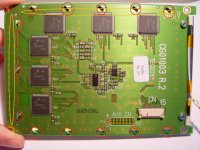
I have had the scopemeter below for several years. The lines showed up shortly after buying it. Fluke does not offer repair parts or displays. My best guess is the elastomer connector between the PCB and LCD is the problem because past removals cleaning of the elastomer have changed, not fixed, the display.
Any suggestion on how I might be able to fix this would be most appreciated.
-Adrien
Any suggestion on how I might be able to fix this would be most appreciated.
An externally hosted image should be here but it was not working when we last tested it.
-Adrien
Last edited:
I've got an older monochrome 100MHz Scopemeter "something or other" with a dead display and have been told by the major repairs shops that it's a basically a flashy paperweight. It failed after less than 5 years, and was the last HP instrument I bought, or will buy.
In the old days we would have called it a boat anchor, but unlike the equipment of yore it doesn't even weigh enough to be decent anchor.
Wish I had better news...
In the old days we would have called it a boat anchor, but unlike the equipment of yore it doesn't even weigh enough to be decent anchor.
Wish I had better news...
Repair for 192 ScopeMeter display lines
aterren,
My company offers the exact repair service you need to correct the lines:
http://www.rightclickcomputer.com/electronics/scopemeter_display/
You can order the repair procedure directly off the website. Typical turnaround time is 7-10 days with an expedited 1-day option.
Joel Friend
Right-Click Computer & Electronics Service
My company offers the exact repair service you need to correct the lines:
You can order the repair procedure directly off the website. Typical turnaround time is 7-10 days with an expedited 1-day option.
Joel Friend
Joel,
Thanks. I am quite interested in this and will likely send you my meter. Could you describe the nature of the repair? Given fluke's history with elastomeric connectors I'm guessing that is the root cause and you've found a source for a replacements. That is very appealing. If you have however found a way to make their current elastomer work for a while then it is not as attractive a solution.
-Adrien
Adrien,
Please send me a message through our website's contact form so we can exchange e-mail:
Right-Click Computer & Electronics Service | Contact Us
I am not permitted to disclose information concerning our restoration procedure on a public forum.
Joel
Please send me a message through our website's contact form so we can exchange e-mail:
Right-Click Computer & Electronics Service | Contact Us
I am not permitted to disclose information concerning our restoration procedure on a public forum.
Joel
Fixed!
I sent my meter off to Joel and here are the results:
The service and results are were good and I'm happy. I just hope the repair is durable... Time will tell.
I sent my meter off to Joel and here are the results:
An externally hosted image should be here but it was not working when we last tested it.
An externally hosted image should be here but it was not working when we last tested it.
The service and results are were good and I'm happy. I just hope the repair is durable... Time will tell.
DIY Fix for black screen lines on a Fluke Scope Meter(199)
I have been able to eliminate the black horizontal lines on my scope, it's been okay for months now!
If you've already taken your scope apart (and it still works) you'll know what I'm talking about.
If not, BE CAREFUL!
You'll need to get to the screen module, and you'll see the glass screen, which has on one edge a huge ribbon cable "glued" to the glass.
This cable carries the connections for the horizontal screen lines, and if any one looses the connection, the horizontal line turns black.
The vertical lines are connected by a "rubber" strip between the circuit board and the back of the glass, this strip has hundreds of insulated conducting "wires' going through it to make the connections, it does not have to be lined up with anything, since the "wires" go straight between the top and bottom.
The ribbon cable was the problem on my scope.
You will need to get the screen and circuit board out of the metal frame by bending the metal tabs on the edges.
You'll need to unfold the screen from the board to get to the area where the ribbon cable is "glued" to the back of the screen.
I used a hot melt glue gun..without glue...and moved it, with a slight pressure, across the back of the ribbon cable where it is glued to the screen.
My glue gun has a metal tip, and it didn't melt the ribbon, but re-established the connections by heat.
(I'm sure a soldering iron would be much too hot)
You probably should make a number of passes with the tip.
Enjoy!
reviving a dead thread because i have this problem with my scope.
R128 can you describe in more detail how you unfolded the screen to access the area where the horizontal-line ribbon cable is glued to the glass? Did you have to disconnect the strip for the virtical wires to do this?
thanks for the help.
R128 can you describe in more detail how you unfolded the screen to access the area where the horizontal-line ribbon cable is glued to the glass? Did you have to disconnect the strip for the virtical wires to do this?
thanks for the help.
To revive this thread yet again, R128 gave good pointers. It is indeed the ribbon cable that makes poor connection on the circuit board and can be corrected by applying mild local heat and slight pressure. This is a very delicate job and I would not recommend to attempt it. Have joelfriend do the job for you.
But for those who can't resist to mess around with the display, be warned, this very very delicate work.
Here are the steps:
Carefully disconnect the data cable and backlight cable from the main board.
Remove the main board.
Remove the metal chassis then remove LCD display from plastic chassis.
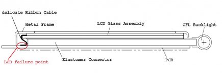
Wearing gloves, carefully undo the tabs which hold the metal frame over the LCD glass assembly.
Be aware the delicate ribbon cable is on the opposite side of the LCD display with respect to the backlight.
Once the metal frame has been removed the LCD may be loose now, be sure there is no chance for dust or contamination to come between the elastomer connector and the LCD glass assembly. Be careful not to stress the ribbon cable.
Now carefully apply mild heat and mild pressure simultaneously to the area on the ribbon cable on the PCB at the locations needed.
Now reassemble LCD in reverse order and with some luck the dark horizontal lines are now functioning again.
But for those who can't resist to mess around with the display, be warned, this very very delicate work.
Here are the steps:
Carefully disconnect the data cable and backlight cable from the main board.
Remove the main board.
Remove the metal chassis then remove LCD display from plastic chassis.
Wearing gloves, carefully undo the tabs which hold the metal frame over the LCD glass assembly.
Be aware the delicate ribbon cable is on the opposite side of the LCD display with respect to the backlight.
Once the metal frame has been removed the LCD may be loose now, be sure there is no chance for dust or contamination to come between the elastomer connector and the LCD glass assembly. Be careful not to stress the ribbon cable.
Now carefully apply mild heat and mild pressure simultaneously to the area on the ribbon cable on the PCB at the locations needed.
Now reassemble LCD in reverse order and with some luck the dark horizontal lines are now functioning again.
Attachments
To revive this thread yet again, R128 gave good pointers. It is indeed the ribbon cable that makes poor connection on the circuit board and can be corrected by applying mild local heat and slight pressure. This is a very delicate job and I would not recommend to attempt it. Have joelfriend do the job for you.
But for those who can't resist to mess around with the display, be warned, this very very delicate work.
Here are the steps:
Carefully disconnect the data cable and backlight cable from the main board.
Remove the main board.
Remove the metal chassis then remove LCD display from plastic chassis.
Wearing gloves, carefully undo the tabs which hold the metal frame over the LCD glass assembly.
Be aware the delicate ribbon cable is on the opposite side of the LCD display with respect to the backlight.
Once the metal frame has been removed the LCD may be loose now, be sure there is no chance for dust or contamination to come between the elastomer connector and the LCD glass assembly. Be careful not to stress the ribbon cable.
Now carefully apply mild heat and mild pressure simultaneously to the area on the ribbon cable on the PCB at the locations needed.
Now reassemble LCD in reverse order and with some luck the dark horizontal lines are now functioning again.
Ok, now you got me wanting to try this out on my scope meter. Yeah,
it started doing the exact same thing, the horizontal black lines
across the screen.
I found the service manual that described the fix, but then I didn't save
it because I thought I had already saved the solution and didn't want to
overwrite it. SHAME ON ME. I haven't been able to find it again and my good friends at Fluke are mum. Imagine that, they will gladly send me
to a service center to have it fixed.
I can also get my meter calibrated for about $670.00. That made me
feel really special.
Any way, to make a long story short, thanks for the post and
I'll take some before and after pics.
Cheers,
Sync
Earlier this year Joel at ScopemeterRepair.com repaired and calibrated my old 105 for $250...
My 199 ScopeMeter has a vertical line on the LCD
I see plenty of references to horizontal lines but my 199 has a vertical line about 1/8" wide near the right side of the LCD.
Any suggestions on that being caused by the same issue? Seems reasonable but, as is typical with me, my problems are inevitably non-standard.
I see plenty of references to horizontal lines but my 199 has a vertical line about 1/8" wide near the right side of the LCD.
Any suggestions on that being caused by the same issue? Seems reasonable but, as is typical with me, my problems are inevitably non-standard.
An externally hosted image should be here but it was not working when we last tested it.
An externally hosted image should be here but it was not working when we last tested it.
I realize this is an old thread but I am having the same problem with my 199.
I would love to just send it to Joel but I live in S.A. so this is not an option.
I got the screen out and undid the metal frame clips and lifted it gently. I can see the ribbon cable but can't "unfold" it to get a better view. The metal frame seems bonded to the glass so this is where I chickened out.
Any additional hints would be appreciated.
Clinton
Fluke Scopemeter 196 B/W Screen Repair w/better Grammer
Disclaimer: If you try this and it does not work… It is not my fault….
Last night I said what the heck and jumped in to see if I could fix my Fluke 196 Scopemeter’s B/W screen...
This is how I did it...
First
Be clean keep fingers off all plastic and glass you have to look through… not heeding this will cause you to redo things a little care would have prevented..
Remove the battery when working with your scope.
There are 12 screws torx/flat blade... Two for the top cover, two for the bottom cover, two to split the case, 2 holding the scope frame to the front half of the scope case (shell) and 4 holding the display in. Not bad.
Ok so the Horizontal lines of the display are connected by the infamous “glued” ribbon cable and the vertical lines are connected to an elastomeric connector.
Do not disconnect any ribbon cables you want to be able to turn on the meter apart to test your work.
Flip the main chassis so that the display is sitting in its half of the case on the left side that puts the main board with the rest of the scope sitting on the right side.
I used a mouse pad placed over the main board frame so at a later time I can flip the display on the main board and power up the meter while apart.
I have read in the past that the elastomeric connector for an LCD is not alignment critical… that is not true…. think about how they work it will come up later.
On the back of the display there are 13 twist tabs that hold a glass and metal frame over the display providing the alignment and pressure needed to keep everything connected….
Carefully align the twist tabs to their respective slots… then supporting the frame flip the display board over onto the mouse pad and gently lift up on the frame… This is where you need to keep things clean (don’t touch anything that you can see through or make sure you go back with a micro fiber cloth and clean your finger prints off).
Inside the frame there are two very thin and possibly fragile strips of isolating rubber these are located inside the metal frame… watch out for them they may fall out, if they do I used an xacto blade to maneuver them into their original position… (I did not want to touch them)….
I started off with missing horizontal lines in my display (7 to be exact).. Researching this you may have read about people using glue guns without glue sticks to heat the ribbon cable, or soldering irons…
The heat source I chose was a small travel iron. With the tabbed frame off the ribbon cable is accessible at both the display and daughter board connection points. The travel iron inspired me because the temperature can be controlled, the heating surface is flat and you can carefully control the amount of pressure you exert….
I set the iron at its highest heat setting waited till it reached temperature and carefully ironed the ribbon cable… I ironed and cooled the cable 4 times over about 20 seconds….
Next I tested my work before I put it all together. I placed the tabed frame over the display, I plugged in the battery and carefully pushed the on button on the scope (don’t press the on button too hard because it is held in place with the pressure of the main board frame…).
Now press on the frame to see if the horizontal lines are gone.. You are simulating all those twist tabs… so think about how much pressure they may exert and remember the back end of the display is being pressed against the frame of the main board (thus the soft rubber mouse pad suggested above) so don’t overdo it…
If everything went well and you press the frame in a way that that simulates the tabs you will see the display the display clean on black bars…
If not try more careful ironing…
I did mention that I started out with horizontal lines… at this point I pressed the frame down and could see that I fixed the horizontal lines but in the middle of the screen I now had a vertical line… aaaghh… The vertical lines of the display are controlled by the elastomeric connector…
What I did now was probably not necessary and probably dangerous but I took a Q-tip dipped it in some good grade alcohol and wiped the elastomeric connector and the daughter board lands once (thinking it was somehow dirty).
What I think was really happening was I had not pushed the display over far enough to make proper alignment…
Next I pushed the display over toward the ribbon cable (you just ironed)… after doing this I once again placed the LCD frame over the display and pressed down on it in a way to simulate the pressure exerted by the twist tabs and verified everything was working and that the vertical line had disappeared. They did..
Take the battery out.
Next step flip the daughter board over holding the fame so it does not drop off and twist the tabs… cross the tabs when you twist them (top right, bottom left, top left, bottom right etc)…
Next replace the four screws for the display and recheck your work…. See how the display looks. If all is good reverse assemble the 8 remaining screws and remember the hand strap….
This worked for me I hope it works out for you. Good luck
Im having the same issue with my fluke 196. So in a nutshell the horizontal cable is not making the proper connection and needs to be reseated. In order to reseat the cable need to heat the glue that secures the horizontal cable and position the cable properly. Is this correct?
Disclaimer: If you try this and it does not work… It is not my fault….
Last night I said what the heck and jumped in to see if I could fix my Fluke 196 Scopemeter’s B/W screen...
This is how I did it...
First
Be clean keep fingers off all plastic and glass you have to look through… not heeding this will cause you to redo things a little care would have prevented..
Remove the battery when working with your scope.
There are 12 screws torx/flat blade... Two for the top cover, two for the bottom cover, two to split the case, 2 holding the scope frame to the front half of the scope case (shell) and 4 holding the display in. Not bad.
Ok so the Horizontal lines of the display are connected by the infamous “glued” ribbon cable and the vertical lines are connected to an elastomeric connector.
Do not disconnect any ribbon cables you want to be able to turn on the meter apart to test your work.
Flip the main chassis so that the display is sitting in its half of the case on the left side that puts the main board with the rest of the scope sitting on the right side.
I used a mouse pad placed over the main board frame so at a later time I can flip the display on the main board and power up the meter while apart.
I have read in the past that the elastomeric connector for an LCD is not alignment critical… that is not true…. think about how they work it will come up later.
On the back of the display there are 13 twist tabs that hold a glass and metal frame over the display providing the alignment and pressure needed to keep everything connected….
Carefully align the twist tabs to their respective slots… then supporting the frame flip the display board over onto the mouse pad and gently lift up on the frame… This is where you need to keep things clean (don’t touch anything that you can see through or make sure you go back with a micro fiber cloth and clean your finger prints off).
Inside the frame there are two very thin and possibly fragile strips of isolating rubber these are located inside the metal frame… watch out for them they may fall out, if they do I used an xacto blade to maneuver them into their original position… (I did not want to touch them)….
I started off with missing horizontal lines in my display (7 to be exact).. Researching this you may have read about people using glue guns without glue sticks to heat the ribbon cable, or soldering irons…
The heat source I chose was a small travel iron. With the tabbed frame off the ribbon cable is accessible at both the display and daughter board connection points. The travel iron inspired me because the temperature can be controlled, the heating surface is flat and you can carefully control the amount of pressure you exert….
I set the iron at its highest heat setting waited till it reached temperature and carefully ironed the ribbon cable… I ironed and cooled the cable 4 times over about 20 seconds….
Next I tested my work before I put it all together. I placed the tabed frame over the display, I plugged in the battery and carefully pushed the on button on the scope (don’t press the on button too hard because it is held in place with the pressure of the main board frame…).
Now press on the frame to see if the horizontal lines are gone.. You are simulating all those twist tabs… so think about how much pressure they may exert and remember the back end of the display is being pressed against the frame of the main board (thus the soft rubber mouse pad suggested above) so don’t overdo it…
If everything went well and you press the frame in a way that that simulates the tabs you will see the display the display clean on black bars…
If not try more careful ironing…
I did mention that I started out with horizontal lines… at this point I pressed the frame down and could see that I fixed the horizontal lines but in the middle of the screen I now had a vertical line… aaaghh… The vertical lines of the display are controlled by the elastomeric connector…
What I did now was probably not necessary and probably dangerous but I took a Q-tip dipped it in some good grade alcohol and wiped the elastomeric connector and the daughter board lands once (thinking it was somehow dirty).
What I think was really happening was I had not pushed the display over far enough to make proper alignment…
Next I pushed the display over toward the ribbon cable (you just ironed)… after doing this I once again placed the LCD frame over the display and pressed down on it in a way to simulate the pressure exerted by the twist tabs and verified everything was working and that the vertical line had disappeared. They did..
Take the battery out.
Next step flip the daughter board over holding the fame so it does not drop off and twist the tabs… cross the tabs when you twist them (top right, bottom left, top left, bottom right etc)…
Next replace the four screws for the display and recheck your work…. See how the display looks. If all is good reverse assemble the 8 remaining screws and remember the hand strap….
This worked for me I hope it works out for you. Good luck
Thanks, Great DIY!!! about the ironing, what was the apprex temp or on wich temp. range (wool,etc..) ? is there a risk to damage the riboon cable ?
Thanks again
- Status
- This old topic is closed. If you want to reopen this topic, contact a moderator using the "Report Post" button.
- Home
- Design & Build
- Equipment & Tools
- Help / Ideas for Repairing Fluke 192 Scopemeter