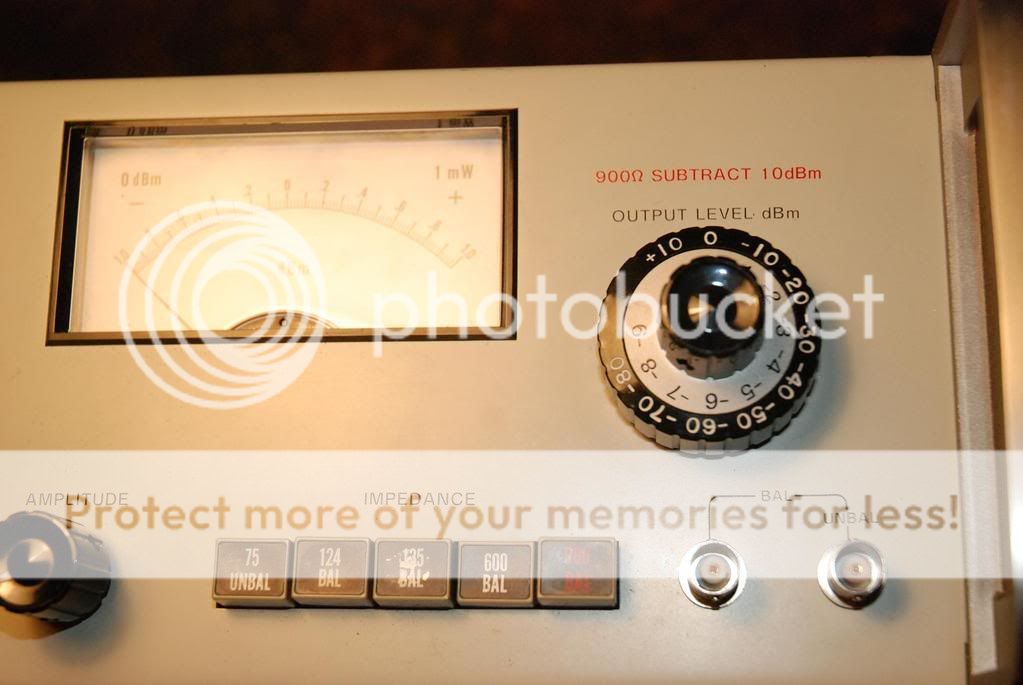
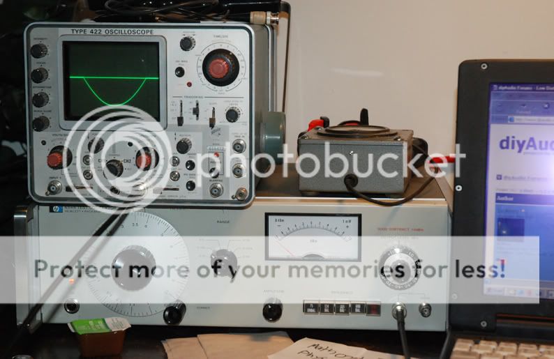
Hi all, I just purchased this HP 654a test oscillator off evil-bay (local pickup though, so no shipping ) for $45. It has option H22( I am guessing it is a rare option because the impedance selector ranges are 75 unbal, 124 bal, 135 bal, 600 bal, and 900 bal) so no 50 ohm, but thats okay.
the main problem with it is that when I adjust the Amplitude control, nothing happens, but adjusting the attenuator does increase/decrease output.
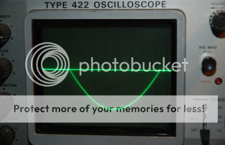
One odd thing, and main reason for my post is that on my scope it shows that there is only lower half of a sine wave, which is def no good.
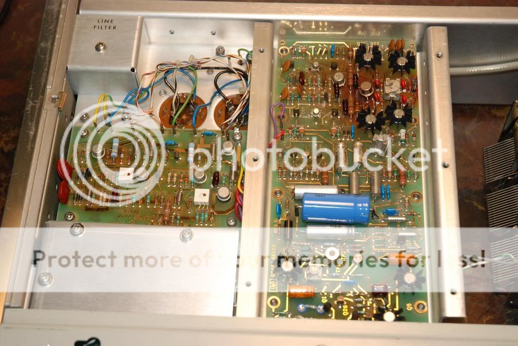
I have taken a bunch of pictures of the insides at perspective fault locations, if anyone wants to see, looks like a tad bit of moisture, but nothing too crazy.
So if anyone out there could help me diagnose this problem, thatd be awesome ( i know anatech is fond of these units). I know repair, but am still iffy with touching something im not supposed to and messing up the cal.
thanks!
regards,
chris
) for $45. It has option H22( I am guessing it is a rare option because the impedance selector ranges are 75 unbal, 124 bal, 135 bal, 600 bal, and 900 bal) so no 50 ohm, but thats okay. the main problem with it is that when I adjust the Amplitude control, nothing happens, but adjusting the attenuator does increase/decrease output.
One odd thing, and main reason for my post is that on my scope it shows that there is only lower half of a sine wave, which is def no good.
I have taken a bunch of pictures of the insides at perspective fault locations, if anyone wants to see, looks like a tad bit of moisture, but nothing too crazy.
So if anyone out there could help me diagnose this problem, thatd be awesome ( i know anatech is fond of these units). I know repair, but am still iffy with touching something im not supposed to and messing up the cal.
thanks!
regards,
chris
I own its forerunner, the 651. But that differs not much.
These are fine IF they work. If they don't, they are a nightmare. Be very careful handling the PCB boards. These are very high impedance structures and any pollution there, especially around the variable frequency cap will disable the thing.
To repair this thing you definitely need a service manual. It is probably around the amplitude stabilisation network or one of the buffer amps is broken.
I have service manuals for the 651B osc. if it is of any help??
My 651B has been my main Osc for years now. love it! very handy. I might be letting mine go soon. My HP339 Dist analyzer is due to be here today. and i haven't decided if i am keeping both or not. I have 4 Osc. now and having 5 just seems to be too much hahahaha
Zc
My 651B has been my main Osc for years now. love it! very handy. I might be letting mine go soon. My HP339 Dist analyzer is due to be here today. and i haven't decided if i am keeping both or not. I have 4 Osc. now and having 5 just seems to be too much hahahaha
Zc
I took some pictures of the test oscillator. tell me what you think!
When I used to work at a communications shop we used alcohol to clean the boards (water damage) but I was reading the service manual for the 652A and it said DO NOT use alcohol, but water and mild detergent instead.
When I used to work at a communications shop we used alcohol to clean the boards (water damage) but I was reading the service manual for the 652A and it said DO NOT use alcohol, but water and mild detergent instead.
so here is the pictures, notice the 900 ohm and lack of 50 ohm..it says option H22
Gold traces!
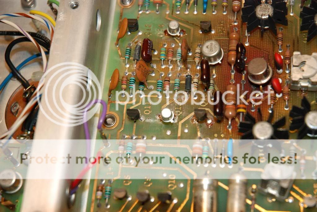
Water damage??
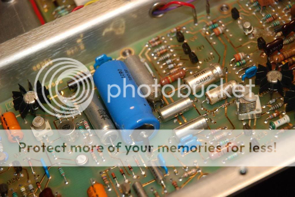
im not sure what that device is to the right of the blue electro cap
and a little more to the right there seems to be some corrosion on the little silver cap?
those resistors got pretty hot!
so any suggestions as to what I should do next...I am not sure what kind of degtergent to use...
and I am still short on a service manual, and the one I have for the 652A doesnt really have that much in common with the 654A
Gold traces!
Water damage??
im not sure what that device is to the right of the blue electro cap
and a little more to the right there seems to be some corrosion on the little silver cap?
those resistors got pretty hot!
so any suggestions as to what I should do next...I am not sure what kind of degtergent to use...
and I am still short on a service manual, and the one I have for the 652A doesnt really have that much in common with the 654A
LOL You keep bbq sauce on your workbench, now that's awesome!
I noticed, like you said, that "those resistors get pretty hot". Well personnally, that's where I'd start to look at the problem. it might be the transistor right next to the two red capacitors, to the right of "those resistors". Well my guess, without having the manual, nor knowing the circuitry of the 654, is that the output amplifier is damaged. It is a transistor amplifier, I can guarantee you that, and one half of it is gone, most possibly the NEGATIVE section, meaning the pnp transistor, because your oscilloscope shows the negative portion of the wave. you didn't have invert on your oscilloscope ON did you?
In any case, that is my first guess, although, there's another place on that circuit board that looks like it had heat damage: near Q26. I have no idea what that section is, but you could remove the transistor and check it. As a matter of fact, that's what I'd do with all the transistors that look damaged, or hot. I am assuming you can do this right?
Oh , and that "device near the blue electrolytic" well judging by the next picture where we can see the other end of it, it is most likely a Light-dependant resistor. You know, a photoresistor and a lamp encapsulated in a opaque or dark tube. I am guessing this is what keeps the amplitude constant depending on the frequency output of the oscillator section.
OK OK I'm done! I sound like a big know-it-all, which I absolutely am not. I just like to help people fix old stuff, because
OLD STUFF RULES
darn font better work
Have you checked to see if both Power supply rails are working??? should have something like + & - 15V at a guess. are both working before and after the V-reg stage?? If yes, then do you have + &- at the output amp stage??
I would start looking for cold solder joints in the area's that got warm.
Zc
I would start looking for cold solder joints in the area's that got warm.
Zc
... and a little more to the right there seems to be some corrosion on the little silver cap?
that looks more like a leaky electrolytic cap

might be worth replacing any small value electro caps, especially any near hot components or any that don't have much polarising voltage ...
i didn't find the manual on BAMA

it'll be real tough without a schematic !!
my guess would be the OP stage - possibly that area of the PCB with the 4 trans with heasinks - maybe you can trace back the OP wiring ?
did you test with both unbal (both + and -) and bal OP ?
dave
PS: just fixed a fluke 1953A for the cost of a junkbox 74S74 - thx BAMA
yeah, its going to be tough without the schematic, maybe ill end up getting one off ebay, but they are about 20 dollars or so..mehh.
I checked BAMA too, I love that site, soo much information.
Ill start poking around with the meter to see what i can find out, but it seems this might have had someone else with thier fingers inside as well!
For the trace on the scope, I had it coming out of the unbal output, for the bal output on 600 ohms its positive, not negative.
Could anyone ask Anatech if he has a copy of the manual? I asked him but he hasnt replied yet and that was two weeks ago.
There might be a bunch of things wrong, though, because the meter still has no movement (slight movement when you change the attenuator, so I know it still works)
I hope I didnt get a dud!
But we will fix it, you guys are great!
thanks again
-chris
( I feel kind of a noob about this.. ) on the output bnc terminals there is one that says unbal, and then going to both of them it says bal...sooooo do i need to use two test cables??
im sorry for my lack of knowledge..haha..but I start electronics engineering school in 5 days!
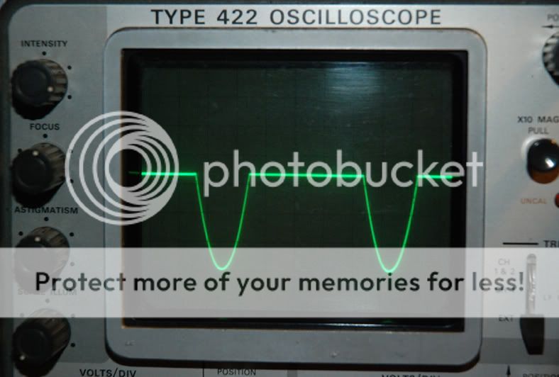
when i have one test cable into the first channel of the scope from the bal/unbal jack, and one other into channel two of scope from the bal only jack i get a psudo sine wave, but it doesnt match up and its not ..i dont know. its all over the place, ill post a pic later ( gotta go to work now) but so when im on 600 ohms the two different output terminals is just for having two outputs to different things...like one to a scope and one to the amp-dist analyzer-scope?
i havent had a chance to trace out the impedance selector circuit to see if its parallel or what..haha
-chris
) on the output bnc terminals there is one that says unbal, and then going to both of them it says bal...sooooo do i need to use two test cables??im sorry for my lack of knowledge..haha..but I start electronics engineering school in 5 days!
when i have one test cable into the first channel of the scope from the bal/unbal jack, and one other into channel two of scope from the bal only jack i get a psudo sine wave, but it doesnt match up and its not ..i dont know. its all over the place, ill post a pic later ( gotta go to work now) but so when im on 600 ohms the two different output terminals is just for having two outputs to different things...like one to a scope and one to the amp-dist analyzer-scope?
i havent had a chance to trace out the impedance selector circuit to see if its parallel or what..haha
-chris
A quick explanation might in order ...
(1) in UNBALANCED mode the output signal is generated between the signal output and ground, ie between the signal and screen of a single BNC connector
(2) in BALANCED mode the output signal is generated between the two signal outputs, ie between the signal of both BNC connectors. In this situation you should NOT assume any relationship between either signal outputs and ground. Often, each output will be an inverted version of the other but this is not guaranteed to always be the case.
Since you connecting the generator to a standard scope input you should connect both outputs to the scope, ie to channel 1 and 2. If you then select “subtract” on the scope you will see the difference signal when the generator is in BALANCED mode.
okay, so I recieved the service manual in the mail, finally. If anyone wants a copy of it, just ask. I should get it put up on BAMA.
so power supply is dead on right. been poking around and it seems the problem is in the balanced amplifier section...? I havent traced it to the component yet. I dont have too much free time ( too much school work to do. gotta love electronics engineering courses)
I get a perfect sinewave out of the Counter Output, so those are my indications so far.
Ooooookay. So I am getting more near the cause of the problem. I have found quite a bit of effects of the problem so far. C10 is no good, C40 is no good (C40 is the one I said had corrosion on it) and C10 is the small capacitor by the transistor with heatsink on the small board. It's part of the Amplitude Control Integrator. The rails are dead on +31.0V and -26.0V.
So the problem is in the Balanced Amplifier, I am pretty sure. I just ran out of time last night to work on it, Ill do some more probing and see what comes of it.
Does anyone know what would be a good compliment to this device?? I am starting my little venture into tube audio amplifiers and I would love to get numbers on my builds and see how I can improve them or whatnot.
I know alot of you have a 33*A distortion analyzer..are they worth the price? And having to potentially repair them as well? ( I do like that they have an AC voltmeter built in that you can use by itself.)
What other things do I need? I have a good DMM, a Tek 422 scope (20Mhz dual trace), this test oscillator...I do have a Heathkit 'harmonic distortion analyzer' but it doesnt work and Im not sure if its worth fixing it as well...its all tube too.
soo, any suggestions to what else I need before I really dive deep into tubes?
(oh, I have a variac, lightbulb current limiter, and the odds and ends..thats about it.)
so I took a closer look at it and I am pretty stumped as to what to do with the Balanced Amplfier. I cant locate it down to a single transitor, so maybe I will just replace them all! haha.
But like i said before A3C10 (sprague 22uF 10% 25V Tantalum) and A2C40 (Sprague 180uF 20% 10V Tantalum) are both no good, so should I possibly replace these first before I replace the transistors and see how it is then?
I just cant seem to find the 'root' of the problem. Which part was the one that made it all fail...
If any of you have those capacitors, I will purchase them off of you. Seems that Digikey doesnt stock them, and they want a high price for them as well.
The full part numbers for the caps are:
22uF- 109D226X9025C2
180uF - 109D187X0010F2-DYP
thanks again you guys for spending the time helping me!
- Status
- This old topic is closed. If you want to reopen this topic, contact a moderator using the "Report Post" button.
- Home
- Design & Build
- Equipment & Tools
- hp 654a test oscillator