Well guys,
I'm back for a while and I hope to eventually finish a projector through to a finished project. For a while I gave up on this DIY projector thing because I could not find a high resolution 16:9 LCD and lens combination that I could be happy with.
Allen over at DIYprojectorcompany and Lumenlabs have now introduced some products that I hope will help me in this persuit.
I have perchaced Allens 135 mm diameter 450 mm FL lens and tested it and it seems to be a better lens that the typical OHP lenses both for brightness and image through size. It also seems to work with a 17 inch LCD and maybe a 19 inch one.
Many will dislike this project because it is large but for me this is easier to work with and impliments all of my ideas that I have pondered over the last couple of years.
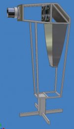
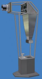
Although the pictures do not show it. This is a roll around self standing projector that will be stored in the corner and moved out for viewing. The wheels are missing on the models.
My intension is to use a 17 inch 16:9 aspect ratio LCD so that I can despense with an anamorphic attachment. The projector uses these main ideas.
1) Deep parabolic reflector to capture more total light and collimate the light into a relatively axial orientation.
2) Enclosed and air cooled light bulb housing which has a UV and IR filter and is cooled with a large heat sink.
3) Light recycling polarizing 45 degree angle reflector made of simple and relatively inexpensive parts.
4) Simple light path. One frenel lens collapsoing collimated light into a longer FL light cone prior to the LCD.
5) No fresnel in LCD to objective light path.
Here was the first conceptual design model before I started working on the deep parabolic reflector.
Hezz
I'm back for a while and I hope to eventually finish a projector through to a finished project. For a while I gave up on this DIY projector thing because I could not find a high resolution 16:9 LCD and lens combination that I could be happy with.
Allen over at DIYprojectorcompany and Lumenlabs have now introduced some products that I hope will help me in this persuit.
I have perchaced Allens 135 mm diameter 450 mm FL lens and tested it and it seems to be a better lens that the typical OHP lenses both for brightness and image through size. It also seems to work with a 17 inch LCD and maybe a 19 inch one.
Many will dislike this project because it is large but for me this is easier to work with and impliments all of my ideas that I have pondered over the last couple of years.
Although the pictures do not show it. This is a roll around self standing projector that will be stored in the corner and moved out for viewing. The wheels are missing on the models.
My intension is to use a 17 inch 16:9 aspect ratio LCD so that I can despense with an anamorphic attachment. The projector uses these main ideas.
1) Deep parabolic reflector to capture more total light and collimate the light into a relatively axial orientation.
2) Enclosed and air cooled light bulb housing which has a UV and IR filter and is cooled with a large heat sink.
3) Light recycling polarizing 45 degree angle reflector made of simple and relatively inexpensive parts.
4) Simple light path. One frenel lens collapsoing collimated light into a longer FL light cone prior to the LCD.
5) No fresnel in LCD to objective light path.
Here was the first conceptual design model before I started working on the deep parabolic reflector.
Hezz
Attachments
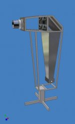
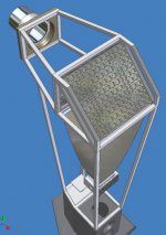
The above picture shows the two peice light engine assembly but consists of a long paramidal light pipe. The next picture shows the upper portion of the deep parabolic light pipe that I will attempt to make out of hand polished aluminum sheet. The large lens is to scale and I have started work on both the lens mounting and focusing mount. I have also build the frame all except for the lower pedestal stand. Real pictures later perhaps.
Attachments
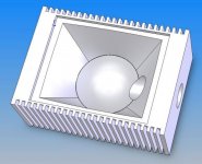
The light recycler reflector relies on simple and relatively easy construction methods. It has a backing of 1 1/2 inch thick MDF to keep the mirror flat. Then mirror reflective mylar film is bonded to the flat surface followed by a 1/4 wave retarding film.
Then square pieces of clear acrylic are bonded in rows with reflective mylar film bonded to all of there sides with the shiny side facing in.
Finally the initial mirror surface is bonded to the acrylic pieces and is a polarizing reflective film that reflects one polarization state at 45 degrees and lest the other pass (from the front). Light of the incorrect polarization state is reflected into the cube and bounces and make two passes through the 1/4 wave retarding film.
The success of this recycling reflector depends on being able to find and inexpensive polarizing reflector that has the correct behavior. I have seen illustrations on some web sites that show this principle.
Any help with sources for the right films would be appreciated.
Hezz
Attachments
Brilliant! What do you think about this recycler idea?
Hezz - Your ideas are brilliant and inspiring.
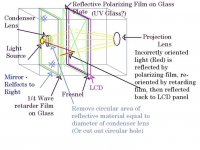
I have simpler ambitions. Would you mind giving me your opinion on my simple design for a light recycler? This design is based on using a bulb with a condenser lens. The light passes from the bulb, through a mirror with a circular area of reflective material removed. It passes through a 1/4 wave retarder that also has a circular area removed. Then it passes through a reflective polarizer (could be film attached directly to the fresnel, although I like the idea of a sheet of UV glass.
Properly polarized light will pass directly through all of these and illuminate the LCD panel. The rest of the light will be relfected back through the retarder, be re-oriented 1/4 wave, then bounce of the mirror, be re-oriented a further 1/4 wave, then pass through the polarizing filter, illuminating the LCD.
Now the big problem: Where do we get the 1/4 wave and 90 degree reflective polarizing films?
Hezz - Your ideas are brilliant and inspiring.
I have simpler ambitions. Would you mind giving me your opinion on my simple design for a light recycler? This design is based on using a bulb with a condenser lens. The light passes from the bulb, through a mirror with a circular area of reflective material removed. It passes through a 1/4 wave retarder that also has a circular area removed. Then it passes through a reflective polarizer (could be film attached directly to the fresnel, although I like the idea of a sheet of UV glass.
Properly polarized light will pass directly through all of these and illuminate the LCD panel. The rest of the light will be relfected back through the retarder, be re-oriented 1/4 wave, then bounce of the mirror, be re-oriented a further 1/4 wave, then pass through the polarizing filter, illuminating the LCD.
Now the big problem: Where do we get the 1/4 wave and 90 degree reflective polarizing films?
Attachments
Honukele,
It's nice to see someone else trying to impliment a light recycler. I have looked at your design and it is quite ingenious. It should quite well and the beauty of it is that it can be easily implimented.
I would make sure that the entire enclosure from the first mirror to the polarizing reflector is lined with highly reflective material on all sides because you will get light bouncing around at all angles and you want to trap all of the light in this area until it can exit with the correct polarization state.
You could also completely surround the light source with reflective material as a lot of stray light goes off to the sides. With your system you could also eventually recycle some of this light if you made the first mirror reflective on both sides. The stray light would bounce around in the first light chamber until it found it's way through the hole and the condenser lens.
Also, as you probably already know make sure to use a spherical reflector behind the light source. In theory you could have light bouncing back into the reflector and out again to eventually be properly polarized.
3M makes some reflective polarizing films called vikitu. They have a web site. Search for Vikitu films.
I found at least one company that makes 1/4 wave plate thin film retarders but I lost the link. If I find it again I will post it here.
Good work and best wishes on your project.
Hezz
Re: 16:9LCD
All 17 and 15 LCD can do 16:9 Count the Pix, or read the service Data, Refrect Light it have been use it on the market for over 20Years, u can use 2 mirrow in 90 Degree angle, or use Curve mirror, use bigger Lens better then Bigger light, My Triplet 8inch
and weight 6lbs ,
All 17 and 15 LCD can do 16:9 Count the Pix, or read the service Data, Refrect Light it have been use it on the market for over 20Years, u can use 2 mirrow in 90 Degree angle, or use Curve mirror, use bigger Lens better then Bigger light, My Triplet 8inch
and weight 6lbs ,
Honukele,
Here is a company I found that makes 1/4 wave retarder films.
http://www.optigrafix.com/qwgrade.htm
Hezz
Here is a company I found that makes 1/4 wave retarder films.
http://www.optigrafix.com/qwgrade.htm
Hezz
Small update
In keeping with my goal as a roll around projector I went and bought a old used office chair at a thrift store for 10 dollars. I dismantled the chair and I will be using the lower roll around support and screw adjuster to mount the projector frame on. This will give me about 4-5 inches of up and down height adjustment.
Hezz
light recycling
This is a great idea since incorrectly polarized light does not get through the LCD panel, and is used in lots of high-end projectors.
But sending all that recycled and re-oriented light just anywhere, does not help: Light has to go through the LCD in a direction that will hit the projection lens, or it adds nothing to the image. So lining the light chamber with reflective material is a waste of time and money. In fact it might actually harm the resolution of the image. Lots of lenses get much sharper when a stop aperature is added to limit the light to rays going in the right directions near the center of the lens.
I think you might want to think about a design that uses an elliptical reflector with a positive lens just past the focal point to make a small parallel beam. Then you can use a polarized reflector to send the incorrectly polarized light to another path for re-orientation. Then add it back to the main path with a beam splitter prism. Then a lens could spread it to a fresnel for the LCD.
Thanks for the reply on the Light Recycler idea. Lining the entire box with reflective surfaces is a good idea. Of course the light will not reflect off of the screen directly to the mirror!
Also still thinking about the light reflector behind the bulb. Ideally you'd want a reflector that focuses ALL of the light onto the condensor lens. Not sure if the Norpro bowl/ ladel accomplish this, or if I should go with a spherical mirror combined with some other reflective surfaces. Guess I'll have to experiment.
Now that we've found the manufacturers of the polarizing films (3M, Optigrafix) the problem seems to be finding the distributors. I'll keep looking, too.
As for the roll-around, idea. That's brilliant. I was thinking of having the projector double as a Sofa end table. (Is that too blasphemous?) You could roll it out when you are watching films/ tv/ games, then roll it away to sit benignly next to the sofa at other times. Do the wheels on your chair lock? Of course you'd have to spill-proof it. I think this will make the idea of having a large wooden box in the living room easier to sell to my wife. I also intend to use veneered plywood and stain it to match the rest of the living room furniture.
Honukele,
good to hear from you. According to a post over at DIYbuildergroup, Onieda makes a high quality stainless steel soup ladle that is perfectly a half sphere. It costs about 11 USD and can be polished to a high shine.
According to other builders that I have discussed light engine designs with the stray light is quite substantial and although you should do everything that you can to get as much initial light to focus correctly with the reflector and the condenser lens, gathering the stray light can improve the brightness of the projector significantly. Especially if the light is recycled.
I think your idea of a projector in a end table is a good one. It is the pinnacle of good design when an object can serve more than one purpose and of course it makes it easier for the wife to accept. In one of my older posts one builder drew up a sketch of a projector in an end table and I though the concept was rather good.
After further study I'm afraid that my light engine design has one major drawback. It can only polarize light in one linear direction and if the LCD does not accept light of this polarization type it won't work. The only way to reverse the polarization orientation would be to turn the light recycler sideways and this is not possible to do and retain the basic overall design.
Hezz
Does anybody know the polarization?
Do we know the polarization orientation of an LCD monitor screen? I am assuming that a sheet of polarized material I can buy, would be oriented in parallel with one edge. Are LCD's light output oriented the same way? I know they work by selectively twisting the polarization between two filters with different orientation. So a filter for the light going into an LCD has to match the orientation of the first filter it hits. But then what if you need to turn the LCD backwards, because you are using a mirror? Then you have to match the filter on the other side, which will be different. How different? 90 degrees?
I guess it would be safest to buy a sheet of polarised material that is big enough to turn it to any angle to match the orientation of the LCD. Then you could cut it to fit the size of the LCD.
I managed to get a few samples from 3M a while ago with this same light idea in mind. While I still think it's a great idea and should be used in some way, I dont see it working with a classic spherical reflector/condenser lens setup. Perhaps with a small lamp and better reflector it would be easier to put a good light recycler to work.
- JCB
www.diybuildergroup.com
www.dbgforum.com
- JCB
www.diybuildergroup.com
www.dbgforum.com
best reflector possible
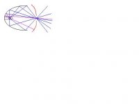
I think the best you can do for a reflector is to combine an elliptical reflector with a spherical reflector to recycle the rays that missed the elliptical surface. Look at the drawing. Blue rays go from the lamp arc to the elliptical reflector, and on the the second focal point of the ellipse. Violet rays are sent back from the red spherical reflector through the lamp arc, and into the elliptical reflector path. The only rays that miss the reflectors go directly from the lamp arc through the hole in the spherical reflector.
You can make the reflectors the right size to give you an diverging beam of light that fits your lower fresnel. For example, if you want to fill a 15" lower fresnel with a focal length of 220 mm, then the diverging light cone should spread to 15" at 220 mm from the second focal point. It is easy to work backwards to see how wide your reflectors have to be to give you any shape light cone you need.
The small focal point at the hole in the second reflector is also an ideal place to put a hot mirror! Now all we need is somebody who can do some aluminum sandcasting or sheet metal stamping of reflector sections.
Attachments
Guy,
As of yet I have been unable to determine the more common polarization orientation for most LCD panels but I assume that they come in both s and p versions and the choice of which type of polarized light to use may have something to do with which state works best for that particular LCD formulation.
You are correct in stating that the correct polarization orientation can be obtained by rotating the polarizer by 90 degrees. This is relatively easy to do. However, as I stated above my light recycler concept is physically hard to rotate. Because it relies on brewsters angle to reflect linearly polarized light which is parallel to the plane of the reflector surface it does not behave exactly like a polarizer. I would have to turn my whole light engine sideways and this would not be possible and retain the upright projector frame configuration. Although it should be able to be implimented if designed from the beginning with a smaller projector where the light engine could be folded to the side instead of down.
Also your eliptical light recycling reflector could possibly be implimented with Honukele's polarization recycler and together they would be very effective.
Hezz
One of the things that I have had to change around in my home theater space was where the television was. It will be necessary for me to retain the Mitsubishi 27 inch television because some members of the family may want to use the regular DVD or VHS player and view something on the TV like the news.
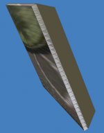
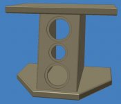
The problem I had was that the television rests on a custom A/V stand that I made and I liked the TV higher than usual so it was in the way of the wall where I needed to project the image. I moved the A/V stand again'st the right hand wall and put the TV on a low table. This has left me with enough wall space to project on but left no place for the center channel speaker except to lay on the floor. So I decided to build a unique tv stand center channel speaker. This is somewhat of a compromise for the big screen projector as it would be more ideal to have the speaker up towards the bottom of the screen but there just wasn't room.
So I designed this pedestal TV stand and center channel speaker combination. I have it built but no pictures as I don't have a digital camera and don't want to go get 35 mm film developed to disc right now.
Here is a picture of the first conceptual solid model. The final was built to high end standards with lots of internal bracing but the outer dimensions and shape remain the same.
Hezz
Attachments
I have a few design updates to post on the progress of my projector.
Yesterday I did some more work on the frame and I welded some parts that I had machined to make the frame attach to the roll around bottom of the office chair that I had gotten from surplus sources.
After, mounting the frame I found that there was too much play and movement. I took some pictures at this stage but I am going to wait to have them developed later as I have more pictures to take.
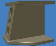
I have come up with a different frame mounting scheme and I post the concept model here. I will continue to use the bottom of the chair for developement until I get the exact height zeroed in. The new base will be made of painted MDF and will house some of the electrical junction boxes and the fan which will blow upwards towards the bulb reflector heat sink assembly.
Two large holes will be cut in the bottom of the base and covered with a couple of used 6.5 inch speaker covers that I have. Maybe with thin felt filter inside to lower dust going in.
The magnetic ballast transformer will be housed in the aluminum shield which is mounted near the bottom next to the fan.
Hezz
Yesterday I did some more work on the frame and I welded some parts that I had machined to make the frame attach to the roll around bottom of the office chair that I had gotten from surplus sources.
After, mounting the frame I found that there was too much play and movement. I took some pictures at this stage but I am going to wait to have them developed later as I have more pictures to take.
I have come up with a different frame mounting scheme and I post the concept model here. I will continue to use the bottom of the chair for developement until I get the exact height zeroed in. The new base will be made of painted MDF and will house some of the electrical junction boxes and the fan which will blow upwards towards the bulb reflector heat sink assembly.
Two large holes will be cut in the bottom of the base and covered with a couple of used 6.5 inch speaker covers that I have. Maybe with thin felt filter inside to lower dust going in.
The magnetic ballast transformer will be housed in the aluminum shield which is mounted near the bottom next to the fan.
Hezz
Attachments
I guess I got the images mixed up as the above does not show the magnetic shield. The transformer will be glued with silicone glue to a thick rubber puck on top of the little pedestal at the bottom of the frame. This is really the mount for the roll around castor assembly but it will serve as a mount for the transformer.
Since the light recycling reflector is an experiemntal thing I have decided to use a first surface mirror at first to get the projector going sooner. Because of the size of the first surface mirror I decided that it might be kind of expensive to buy so I am gong to hand grind my own. It will be made from a 3/4 inch thick piece of aluminum and machined on the rear to make it more stable. It will give me something to do on the Mazak VTC-16 at school.
I think that you can see the back of the mirror and it's mounting scheme in this model picture. Stay tuned, I will be posting pictures and information on how I'm making the mirror.
Hezz
Attachments
- Status
- This old topic is closed. If you want to reopen this topic, contact a moderator using the "Report Post" button.
- Home
- General Interest
- Everything Else
- The Moving Image
- DIY Projectors
- 17 inch 16:9 assault on high end project