Ah, thanks ") but why doesn't it say anything about that in the service manual.. Strange stuff.
but why doesn't it say anything about that in the service manual.. Strange stuff.
I was also wondering about the BU thing. It would make sence that it is used for the pich control. I don't care about it. If would lose it, I won't miss it. it would be great to get the details!
but why doesn't it say anything about that in the service manual.. Strange stuff.I was also wondering about the BU thing. It would make sence that it is used for the pich control. I don't care about it. If would lose it, I won't miss it. it would be great to get the details!
EC8010 said:
Thanks for that. If you don't have a means of decompressing .rar files:
http://www.download.com/3000-2250-10007677.html
Hi.
I cannot get this link to work.
Any ideas???
Has any one successfully downloaded it??
If so, please post to :- http://www.yourfilelink.com/
And I can download from there if you post the url
Andy
EC8010 said:I've just had the lid off. X601 is an 8.4672MHz crystal and that's also what it says on the parts list of the manual, I wondered how I'd got it wrong, so I went back to the diagram...
Yes, that's what I also saw, but how does this go together with the frequencies speficied the the DAC datasheet (3.5 System Clocking)?
Thank you, Philips. Let's make things better, huh?
Oh, they have given up on that
Now it is "Sense and Simplicity" 
Sounds like real fun
Let me tell you want I might want to do to my CD-5400:
- replace opamps with AD8620
- remove muting, and maybee replace it with a relay
- remove or replace out caps.
- replace dac with a CS4398
- do some power supply tweaks
- replace crystal stuff
I guess, I'll first replace the opamps. But I'll take it slowly
I intend to start by improving the clock - that's a serious weakness. I might replace the muting with relays, and might well replace the coupling capacitors. I have a pair of AD8620, so they might go in. Frankly, the change that will make the biggest difference is the clock. Everything else is just polishing.
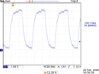
Hmm, 16.89 is also not in the DAC datasheet. The closest is 16.9344 Mhz.... Could that be a match? That would also account for the 8.4672 Mhz crystal I guess (it's half of that.
But how to get on now? Rip out the that BU... thing, and replace it with a simple and good clock circuit?
But how to get on now? Rip out the that BU... thing, and replace it with a simple and good clock circuit?
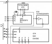
That's trickier. At first, I was worried that the micro was really the master clock, but if you look, it uses the 16.9344MHz clock that arrives on pin 46. But the circuit diagrams and data sheets don't make sense to me. According to the Rohm BU2630 data sheet, pins 7, 8, and 9 are determinedly digital inputs, yet the Marantz diagram shows them connected to analogue signals. Something is wrong here.
What we expect to find is some sort of a master oscillator, followed by a frequency synthesizer to allow that frequency to be varied. We expect that variable frequency to go to the CD motor servo to control the speed of data read off disc and we expect it to go to the DAC to allow the DAC to cope with data having a variable sample frequency. We would expect that when variable pitch isn't engaged that the multiplication ratio of the frequency synthesizer would be an integer (2).
What we expect to find is some sort of a master oscillator, followed by a frequency synthesizer to allow that frequency to be varied. We expect that variable frequency to go to the CD motor servo to control the speed of data read off disc and we expect it to go to the DAC to allow the DAC to cope with data having a variable sample frequency. We would expect that when variable pitch isn't engaged that the multiplication ratio of the frequency synthesizer would be an integer (2).
Attachments
EC8010 said:in 46. But the circuit diagrams and data sheets don't make sense to me. According to the Rohm BU2630 data sheet, pins 7, 8, and 9 are determinedly digital inputs, yet the Marantz diagram shows them connected to analogue signals. Something is wrong here.
Exactly what I found! So I'm not going nuts?
I dug a bit further and found that the pins are actually refering to TMP87PS71AF (IC71). There pins 34,35 and 36 are actually labled SDA, SCL and PLL, and this is the uC that controls the whole thing, and they are connected to a general purpuse IO pin. So I guess those are used to setup pitch stuff.
I guess, you can just leave it away
Might be some obfuscation in the manual to make it harder to understand?
So I guess, you'll just have to insert a fesh clock into the point labled "DSP" and cut the rest loose?
4real said:I guess, you can just leave it away
Might be some obfuscation in the manual to make it harder to understand?
The manual is certainly clear as mud.
There's only one way of proving it. Put a fixed 16.9344MHz clock in to feed the DAC and the controller and see if it works. Watch this space...
- Status
- This old topic is closed. If you want to reopen this topic, contact a moderator using the "Report Post" button.
- Home
- Source & Line
- Digital Source
- Marantz CD5400 clock replacement