 . I will just use a default breadboard to make mine I guess.
4real said:Still not sure on where to put the inductor though... Any thoughts?
Do you mean the ferrite bead? I put it as close as I could reasonably get to the +5V pin without it touching the case (which is at 0V).
The advantage of hand-made PCBs is that you can have nice old-fashioned curves.

EC8010 said:Do you mean the ferrite bead? I put it as close as I could reasonably get to the +5V pin without it touching the case (which is at 0V).
No, I mean an extra inductor before or after the regulator for extra filtering. It is not in the Tent schematic.
The advantage of hand-made PCBs is that you can have nice old-fashioned curves.
Yes, but the disadvantage is that you need stuff to make it
If you're going to add an inductor, I'd put it before the regulator so that the regulator isn't exposed to RF that it might demodulate.
Parts needed for making PCB:
Enamel paint
00 paint brush
Ferric chloride solution
Plastic lunch box (etching tray)
Paint stripper
Toothbrush (for paint stripper)
Rubber gloves
Apart from the ferric chloride, it's all available in the high street.
Parts needed for making PCB:
Enamel paint
00 paint brush
Ferric chloride solution
Plastic lunch box (etching tray)
Paint stripper
Toothbrush (for paint stripper)
Rubber gloves
Apart from the ferric chloride, it's all available in the high street.
EC8010 said:If you're going to add an inductor, I'd put it before the regulator so that the regulator isn't exposed to RF that it might demodulate.
Okay, will do that then
About the PDB making: yes I know it's fairly simple, but I'm not trusting myself with the hand painting and stuff
I like the PC way better. I guess I should just try it ones.Just another quick question:
Is the servo clock inverted or not. You did put the new clock in front of the invertor input, so it probably is, but if you look at the service manual, both clock are inverted. On the other hand, in another place in the manual, only the servo clock is inverted....
So what is it? If it is inverted I will include the invertor on the clock PCB, and use small 50 Ohm coax to bring the clocks to the chips.
Good point. Unmodified, both the servo and the DAC have clocks that pass through invertors so both devices see the same polarity. As it stands, my modification means that one clock is inverted with respect to the other. Perhaps I should take the servo clock through both invertors. I left the invertor in because I wanted it to buffer the servo and path away from the DAC.
Regarding 50 Ohm co-ax, what is the source impedance of a CMOS logic chip? Unless you're matched to the cable, there's no advantage that I can see.
Regarding 50 Ohm co-ax, what is the source impedance of a CMOS logic chip? Unless you're matched to the cable, there's no advantage that I can see.
EC8010 said:Regarding 50 Ohm co-ax, what is the source impedance of a CMOS logic chip? Unless you're matched to the cable, there's no advantage that I can see.
That's true... I can't seem to find the input impedance in the DAC datasheet... So, simple cable will do I guess. Thanks for noticing!
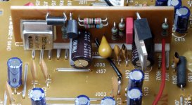
I got my Tent clock in yesterday. The rest of the parts should be in tomorrow.
Can anyone confirm that the orriginal clock of the servo and DAC are ouf of phase? I don't have a scope at home to check. If so, I can use a simple invertor on the clock board and bypass all of the clock stuff on the Marantz board.
Can anyone confirm that the orriginal clock of the servo and DAC are ouf of phase? I don't have a scope at home to check. If so, I can use a simple invertor on the clock board and bypass all of the clock stuff on the Marantz board.
On my CD5400 board, the DAC and servo clocks were originally the same phase. I now have one inverted and it seems to work. When I can work up the enthusiasm I will correct the inversion to the servo and see if it makes any difference. The reason I left the invertor in circuit was that I didn't want the Tent clock to have to drive two unterminated transmission lines of unknown impedance and distort the waveform.
Agreed, the Tent info says it can drive three inputs, and if they were all close together, I would let it drive the DCA and the servo directly. My concern was for the shape of the waveform. At 17MHz, transmission line effects come into play and the tracks are highly unlikely to be terminated correctly. Further, connecting two lines in parallel is asking for trouble. That is why I wanted to drive the DAC directly, but buffer the servo. You could always put a buffer on your board and use it to drive the servo, but drive the DAC directly.
- Status
- This old topic is closed. If you want to reopen this topic, contact a moderator using the "Report Post" button.
- Home
- Source & Line
- Digital Source
- Marantz CD5400 clock replacement