Thought I'd share this as I have not seen mention of it on this thread:
I've recently set up separate power supplies for the DAC and decoder (with separate transformers, diodes, smoothing caps, voltage regs feeding each). I did the DAC first, followed by the decoder. The biggest improvement in SQ was when I did the decoder. This surprised me as I thought it would have been the other way round.
Clarity has improved, enabling one to hear further into the mix, with better separation side-to-side and front-to-back. With a well-produced CD there is a greater sense of 'musicians in the room'. Also a poorly-produced CD is shown up for what it really is – nasty!
Hey guys,i wonder if i can remove R149/150,R127/128 from my cd63...i have allready short the fuses as "higlander" suggested.Do i gain anything in sound quality or what the benefits are.Do i have to remove those resistors or short them?
I love questions like this...........whilst I realise this thread is a bit long just to read through, its not a particularly intelligent question!!!
Read the 1st few post and there is a list of things to do which is still in most part a very good list. If you ask about things from this list you will get advise here from the guys. Also, download the service manual and find the resistors you are talking about the you will start to learn.
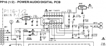
All 4 resistors are in the +/-10v supply to 2 or the 3 driver IC chips. The resistors that carry power to the 3rd driver IC are R164 & R165.
If you remove the resistors, there will be no power to the sled motor, laser, focus and radial so none of those will work!!!
If you short them out, then all of the devices will be directly sharing the same supply. The idea of the resistors is that in addition to some current protection, they help to keep the noise down on the rail for each device. A better way to do it is to use an inductor..................see Rays list, the pattern repeats on every psu rail to every device in the player.
An even better way to do it is to regulate the 10v feed at 8v and use a pair of separate regs (7808/7809)on each driver IC but that's a bit more tricky to implement until you know what you're doing but its well worth it
")
I love questions like this...........whilst I realise this thread is a bit long just to read through, its not a particularly intelligent question!!!
Read the 1st few post and there is a list of things to do which is still in most part a very good list. If you ask about things from this list you will get advise here from the guys. Also, download the service manual and find the resistors you are talking about the you will start to learn.
All 4 resistors are in the +/-10v supply to 2 or the 3 driver IC chips. The resistors that carry power to the 3rd driver IC are R164 & R165.
If you remove the resistors, there will be no power to the sled motor, laser, focus and radial so none of those will work!!!
If you short them out, then all of the devices will be directly sharing the same supply. The idea of the resistors is that in addition to some current protection, they help to keep the noise down on the rail for each device. A better way to do it is to use an inductor..................see Rays list, the pattern repeats on every psu rail to every device in the player.
An even better way to do it is to regulate the 10v feed at 8v and use a pair of separate regs (7808/7809)on each driver IC but that's a bit more tricky to implement until you know what you're doing but its well worth it
UV101,thank you for the info,but i did look on the service manual and the differences between 63 and 63mkii...so R149,150,164,165, are shorted with jumper wire.Am i missing something here??
UV101,thank you for the info,but i did look on the service manual and the differences between 63 and 63mkii...so R149,150,164,165, are shorted with jumper wire.Am i missing something here??
From Ray's web site:Marantz CD53/63 mkII/SE/KI
OK I see where you are coming from as they are listed as mods in the KI version.
R149&150 are the inline feed resistors for Q106 which is the driver IC for laser Focus and Radial. Short them out and you will have the same as a KI.
R164&165 are the inline feed resistors for QM01 which is the driver IC for the spin motor and sled. Short them out and you will have the same as a KI.
The point of the resistors is explained in my previous post but they will serve to current limit supply to those IC's. Remove them and you remove as restriction in the current path which may allow the device to respond quicker to any changes. Like all things, there are 2 side to every story. Here its demand vs. noise separation on the rails.
I believe they are used originally for circuit protection and as such I'd just short them out.........
......as I said before you could also look at separate regulation
Something like this.....repeat for the other driver IC's
Attachments
Last edited:
OK I see where you are coming from as they are listed as mods in the KI version.
R149&150 are the inline feed resistors for Q106 which is the driver IC for laser Focus and Radial. Short them out and you will have the same as a KI.
R164&165 are the inline feed resistors for QM01 which is the driver IC for the spin motor and sled. Short them out and you will have the same as a KI.
The point of the resistors is explained in my previous post but they will serve to current limit supply to those IC's. Remove them and you remove as restriction in the current path which may allow the device to respond quicker to any changes. Like all things, there are 2 side to every story. Here its demand vs. noise separation on the rails.
I believe they are used originally for circuit protection and as such I'd just short them out.........
......as I said before you could also look at separate regulation
Something like this.....repeat for the other driver IC's
uv101,thank you...this is a far better alternative and explain in detail.Thanks a lot.
I've tried it in the past, but didn't find any significant improvements.
That seems to make sense to me, since all internal biassing is done with current sources inside the opamp. If you raise the supply voltage, all you basically do is create more headroom (which isn't needed for a 2Vrms output signal) and increase the heat dissipation.
That seems to make sense to me, since all internal biassing is done with current sources inside the opamp. If you raise the supply voltage, all you basically do is create more headroom (which isn't needed for a 2Vrms output signal) and increase the heat dissipation.
Now i have another silly question.Has any one tried raising the LM4562NA voltage from +/-11.8v (cd63 service manual) to 14 or 15v on them and gain any benefit on SQ?
On all of my 8 mods I used +/- 15V for the opamps. However most of the mods used Discrete Opamps like Burson or Audio GD instead of LM4562. Cant say if there is improvement in SQ but according to Brent of Fidelity Audio in his early mods he also used 15V instead of 12V. He mentioned that it is better.
That will sound even better than opamps
Make sure you use a nice set of regulators.
Whilst we're talking about the output stage...
I have one of your DOS boards, Ray. If I populate this with good quality parts, will the sq be better than what I have already? (HDAMs have been bypassed, opamps replaced with LME49720HA, and the output stage powered by a separate Tx with smoothing caps and power regulators.) I plan to use the separate Tx and power supply to feed the DOS.
Thanks in advance to anyone who may know the answer.
Yep, it will sound better than what you have now. Good parts for the filter are very important, you can use my partslist as a guide. Another one: a good quality output-cap. I currently use Mundorf EVO's (Silver//Gold) and they sound very good. Mundorf Supreme are even better, but even more expensive.
Good regulator are also a must, two for each channel is the best solution.
Good regulator are also a must, two for each channel is the best solution.
Yep, it will sound better than what you have now. Good parts for the filter are very important, you can use my partslist as a guide. Another one: a good quality output-cap. I currently use Mundorf EVO's (Silver//Gold) and they sound very good. Mundorf Supreme are even better, but even more expensive.
Good regulator are also a must, two for each channel is the best solution.
Thanks very much, Ray.
That will sound even better than opamps
Make sure you use a nice set of regulators.
Thanks Ray...you mean other type than the lm317/337 which i have allready install?
Yes, the consensus seems to be that special low noise regs are required for the DOS.
Examples:
Fidelity Audio S-Power
Tentlabs Shunts
Paul Hynes Series Regs
I am still running with 7812/7912 regs, and although the noise floor is audibly higher than op-amps (albeit still silent at safe listening volume), I still prefer the sound of my DOS over the LM4562HA op-amps that I was running previously.
I like building things myself, so I bought a Jung/Didden SuperReg PCB from the DIYAudio store and plan to try that on my DOS soon.
I think Jan 2012 I posted I was about to fit my Kwak Clock 7 into my CD67OSE......I have now got around to doing it and have the player apart, Xtal fitted to clock and ready for it to go in However....where do I terminate the -V and +v supply to the clock (I know where to terminate the ground to)
Thanks
Tom
(posted on behalf of "Honda Z50M" because he's forgotten his password like numpty and changed his email address so can;t get a reminder)
Thanks
Tom
(posted on behalf of "Honda Z50M" because he's forgotten his password like numpty and changed his email address so can;t get a reminder)
- Home
- Source & Line
- Digital Source
- Marantz CD63 & CD67 mods list