Hi,
as I like to play first time with various DAC chips outside CDP as there are TDA1541, PCM56, PCM58 and PCM1702... and in the data sheets signals always have different names, I am lost.
For TDA1541, how can CS8412 be connected to SAA7220 ?
And which OS filter I best use for other DAC chips ?
I have SM 5813 and SM 5841.
In SM5841 data sheet I saw sample/hold used with two PCM58. Why ?
Main problem is that in SM5813 datasheet I see 4 signals input but CS8412 has only 3 signals output.
How do I have to connect CS8412 to SM5813 to use above PCM chips ?
Bernhard
No.......it has 4......
Crystal calls them:
MCK, SCK, FSYNC and SDATA.
Don't ask why they make it so hard to understand................
Jocko
Crystal calls them:
MCK, SCK, FSYNC and SDATA.
Don't ask why they make it so hard to understand................
Jocko
CS8412 to SAA7220.
CS8412 OUTPUT FORMAT 2
SDATA => DAAB
FSYNC => WSAB
SCK => CLAB
MCK => XIN
CS8412 to SM5813.
CS8412 OUTPUT FORMAT 5
SM5813 CKDV = HIGH
SM5813 CKSL = LOW
SM5813 COB = HIGH
SDATA => DIN
FSYNC => LRCI
SCK => BCKI
MCK => XTI
CS8412 OUTPUT FORMAT 2
SDATA => DAAB
FSYNC => WSAB
SCK => CLAB
MCK => XIN
CS8412 to SM5813.
CS8412 OUTPUT FORMAT 5
SM5813 CKDV = HIGH
SM5813 CKSL = LOW
SM5813 COB = HIGH
SDATA => DIN
FSYNC => LRCI
SCK => BCKI
MCK => XTI
The FORMAT depend on the Digital Filter chip you are using ??
How you can operate the SC8414 in 2 Format or 5, ?
please
How you can operate the SC8414 in 2 Format or 5, ?
please
CS8412 to SAA7220.
CS8412 OUTPUT FORMAT 2
SDATA => DAAB
FSYNC => WSAB
SCK => CLAB
MCK => XIN
CS8412 to SM5813.
CS8412 OUTPUT FORMAT 5
SM5813 CKDV = HIGH
SM5813 CKSL = LOW
SM5813 COB = HIGH
SDATA => DIN
FSYNC => LRCI
SCK => BCKI
MCK => XTI
Hello
And how can the CS8414 be connected to the SAA7030 ?
And the SAA7030 would be connected to a TDA1541A.
I think of that because the CS8414 do have SPDIF input.
Here is the SAA7030 data sheet;
http://www.elenota.pl/upload/saa7030.pdf
Thank
Bye
Gaetan
Last edited:
Hello
And how can the CS8414 be connected to the SAA7030 ?
Not without some difficulty.The SAA7030 expects the audio data to be in offset binary form. The CS8414 outputs two's complement data. Somewhere buried in the forum is a circuit to convert from OB to TC.
Not without some difficulty.The SAA7030 expects the audio data to be in offset binary form. The CS8414 outputs two's complement data. Somewhere buried in the forum is a circuit to convert from OB to TC.
Hello
I will look for that circuit to convert from OB to TC.
And for SAA7030 to TDA1541A, any suggestions ?
Thank you
Bye
Gaetan
Hello
I will look for that circuit to convert from OB to TC.
And for SAA7030 to TDA1541A, any suggestions ?
Thank you
Bye
Gaetan
See Table 1 on page 5 of the TDA1541A datasheet.
LAT => LE
/CLFD => BCK
DLFD => DATA L
DRFD => DATA R
As the output of the SAA7030 is only 14 bits and, as far as I can surmise from the datasheet (best check with a 'scope), the sign bit/MSB is not extended, you will need 16 clock cycles to correctly align the 14bit SAA7030 data with the TDA1541A's 16bit input latch.Again more glue logic.
Last edited:
See Table 1 on page 5 of the TDA1541A datasheet.
LAT => LE
/CLFD => BCK
DLFD => DATA L
DRFD => DATA R
As the output of the SAA7030 is only 14 bits and, as far as I can surmise from the datasheet (best check with a 'scope), the sign bit/MSB is not extended, you will need 16 clock cycles to correctly align the 14bit SAA7030 data with the TDA1541A's 16bit input latch.Again more glue logic.
Hello
Yes, true, it take 16 bit input and give out 14 bit with noise shaping to imitate 16 bit.
Humm... 14 bit and more glue logic.
Maby I should go to the analog shift registered dac schematic (an analog 4x OS) that I have received from a friend by email.
But an analog shift registered dac like this one may have more jitter ?
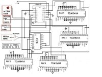
Included the analog shift registered dac schematic.
Thank
Bye
Gaetan
Attachments
Last edited:
Im searching to death for the OB to TC schematic (to connect a cs8414/Dir9001 to a saa7030. The i2s to offset binary schematic) help!!!
- Status
- Not open for further replies.
- Home
- Source & Line
- Digital Source
- How connect CS8412 to OS filter ?