Looking at the schematics, I think the CD723 would benefit from the TDA7072 and TDA7073 BTL drivers beeing referenced to +10V and -10V instead of +10V and ground. It would keep the ground clean of the servo currents and I think it should be a simple mod working without further modifications.
I might be wrong, it's just an idea and I haven't tried it yet. Dissipation on the driver might be too high.
I might be wrong, it's just an idea and I haven't tried it yet. Dissipation on the driver might be too high.
I found a thread concerning LM317 voltage adjustment. Even the most obvious answers are sometimes very hard to find if you have no idea what to look for (I didn't know that the output voltage is set by resistors  )
)
http://www.diyaudio.com/forums/showthread.php?s=&threadid=3300&highlight=
And the most recommended diode type seems to be HEXFRED which seems to be also the most expencive
)http://www.diyaudio.com/forums/showthread.php?s=&threadid=3300&highlight=
And the most recommended diode type seems to be HEXFRED which seems to be also the most expencive
Re: PSU Design
Well - at last I've finally got something that is worth putting all of this effort into. Took some hints from KYW and Dave and Jean-Paul and found an Arcam Delta 70.2. Now I would like to apply all of the PS design to this CDP and it therefore requires some changes to the implimentation.
If this is deviating too far from the original Philips CD723 discussion - then we can take it up in another thread - maybe this one one:
How to put a clock in an Arcam Delta 70.2
The first area I would like to address is the power supply to the audio PCB. At present it has a separate 15V + 15V 12VA TX supplying +/-20Vdc. This is filtered by 1000uF - 6R8 - 1000uf. LM7805/7905 regulate the +/-5V, and LM337 regulates the -15V for the TDA1541AS1. Discrete regulation is used to supply +/-12V for the discrete I/V and the NE5532 opamps.
Farguar and Jean-Paul have suggested (in the Arcam thread) replacing this TX with a better one. My 22V + 22V 25VA unit could be used here - with some additional filtering or pre-regulation.
So - now I'm thinking of making a small board with the new TX, some Schottky diodes, RC filtering and maybe a pre-reg. this could then be fed into the audio board - after the original rectifier.
Any ideas on the best way to do this would be most appreciated.
150mA should be enough to supply positive and negative voltages each. I was thinking of something like 10R/220u/10R/1000u - LM317 - connect to audio board - 10R/1000u/6R8/1000u - existing regs. This supplies the LM317 pre-reg with 26V, 420mV of "peak to peak", a conduction time of almost 5mS and current peaks of 0.5A. The pre-reg could then be set to 20V to supply the PCB.
Is this good enough and does it still satisfy the 6db rule and timeconstants?
I obviously need a refresher course on this!
Another option would be to omit the pre-reg and insert 15R/100u/20R before the existing 1000u/6R8/1000u. This would give 19.3V to the regs with 34mV of "peak to peak", a conduction time of almost 6mS and current peaks of 0.4A.
This seems quite good - but I'm a bit concerned about the no-load voltage being to high at over 30Vdc. The Kill circuit is fed before the regs, which is currently 20Vdc!
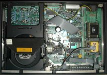
Here is a picture of the inside of the Delta for you to oogle at.
Well - at last I've finally got something that is worth putting all of this effort into. Took some hints from KYW and Dave and Jean-Paul and found an Arcam Delta 70.2. Now I would like to apply all of the PS design to this CDP and it therefore requires some changes to the implimentation.
If this is deviating too far from the original Philips CD723 discussion - then we can take it up in another thread - maybe this one one:
How to put a clock in an Arcam Delta 70.2
The first area I would like to address is the power supply to the audio PCB. At present it has a separate 15V + 15V 12VA TX supplying +/-20Vdc. This is filtered by 1000uF - 6R8 - 1000uf. LM7805/7905 regulate the +/-5V, and LM337 regulates the -15V for the TDA1541AS1. Discrete regulation is used to supply +/-12V for the discrete I/V and the NE5532 opamps.
Farguar and Jean-Paul have suggested (in the Arcam thread) replacing this TX with a better one. My 22V + 22V 25VA unit could be used here - with some additional filtering or pre-regulation.
So - now I'm thinking of making a small board with the new TX, some Schottky diodes, RC filtering and maybe a pre-reg. this could then be fed into the audio board - after the original rectifier.
Any ideas on the best way to do this would be most appreciated.
Kuei Yang Wang said:Konnichiwa,
If we "design in" your 22V/0.5A Transformer and use 22R/100u/10R/2,200uF/10R/2,200uF/10R/2200uF we get 26V DC with 0.5mV peak-peak ripple. Peak currents (for 50mA DC out) are below 0.2A and the current draw is very "rounded", almost a nice sinewave. nearly 4mS conduction time equal 72degrees conduction angle.
Comparing this (for fun) with a single 4,700uF Capacitor has a conduction angle of 27 Degrees and nearly 0.5A peaks with 32V DC overlaid with 90mV Peak-Peak ripple.
150mA should be enough to supply positive and negative voltages each. I was thinking of something like 10R/220u/10R/1000u - LM317 - connect to audio board - 10R/1000u/6R8/1000u - existing regs. This supplies the LM317 pre-reg with 26V, 420mV of "peak to peak", a conduction time of almost 5mS and current peaks of 0.5A. The pre-reg could then be set to 20V to supply the PCB.
Kuei Yang Wang said:Konnichiwa,
You can increase the timeconstant if you like. There are no hard and fast rules, except perhaps the 6db rule.
Is this good enough and does it still satisfy the 6db rule and timeconstants?
I obviously need a refresher course on this!
Another option would be to omit the pre-reg and insert 15R/100u/20R before the existing 1000u/6R8/1000u. This would give 19.3V to the regs with 34mV of "peak to peak", a conduction time of almost 6mS and current peaks of 0.4A.
This seems quite good - but I'm a bit concerned about the no-load voltage being to high at over 30Vdc. The Kill circuit is fed before the regs, which is currently 20Vdc!
Here is a picture of the inside of the Delta for you to oogle at.
Attachments
CDM4/19, CDM4/31
Hello, I am a new member to this wonderful forum, I need Help on fixing a B&O CD7000 player, The CD uses CDM4/13, but I think I can use CDM4/31, so I am looking for one, also if the Original B&O servo board will work on CDM4/31, The B&O servo Board has the usual Ic's, Meaning TDA 5709, TCA0372DP2, motor control: 4560D,and corde IC: TDA5708, with corde #:6105 1 JG 923 00927. Thank you all.
Hello, I am a new member to this wonderful forum, I need Help on fixing a B&O CD7000 player, The CD uses CDM4/13, but I think I can use CDM4/31, so I am looking for one, also if the Original B&O servo board will work on CDM4/31, The B&O servo Board has the usual Ic's, Meaning TDA 5709, TCA0372DP2, motor control: 4560D,and corde IC: TDA5708, with corde #:6105 1 JG 923 00927. Thank you all.
hello, Bricolo, the original Laser cdm4/13 no longer reads Cd's just sping at high speed and then stops. The problem started like this, the Cd player will play a song or too then shuts it self off, usual B&O when finishes playing a Cd, but this one will just stop at one to two tracks. So I replaced the Cap 33mfd on the servo Board, and checked the Laser Current, I have what B&O says I should have 50mV . But now It just sping and shuts off.
Hi,
I was thinking today about these mods to a cd723:-
1. Convert EIAJ to I2S so you can add an I2S dac with the schematic here http://www.diyaudio.com/forums/showthread.php?postid=702826#post702826.
2. Add a tda1541a with a transistor output stage (mabe Jocko's easy I/V)
I'm interested to hear what the combination of VAM1201, and tda1541a would sound like.
Has anyone tried this? (obviously not using a digital receiver chip)
Kind regards,
Ashley.
Hi Fin,
I haven't looked at this thread for ages - you certainly have some staying power!
My conclusion is that the CD723 is only worth modding if you are aiming to better modern players up to about £300.
Your Delta 70.2 with 2 mods will blow most CDPs up to about £2K clean out of the water. All you have to do is disable the digital o/p as per John W's instructions and change the NE5534s to OP27s. The rest of the player is already rather good.
Cheers,
Dave
ash_dac said:Hi,
I was thinking today about these mods to a cd723:-
1. Convert EIAJ to I2S so you can add an I2S dac with the schematic here http://www.diyaudio.com/forums/showthread.php?postid=702826#post702826.
2. Add a tda1541a with a transistor output stage (mabe Jocko's easy I/V)
I'm interested to hear what the combination of VAM1201, and tda1541a would sound like.
Has anyone tried this? (obviously not using a digital receiver chip)
Kind regards,
Ashley.
In the thread regarding the Hack for the CD723 you probably missed one point: the hack not only disables (at will) oversampling but also allows IIS output without the need of an external circuit, leaving the choice of the DAC up to you.
Cheers
Andrea
Andrea,
Thank you for the information.
Sorry I forgot that with the hack you can select the different digital formats.
Have you interfaced to a tda1541a with I/V ?
I found that the 'father' of the tda1545a device had an ok linearity!
see:- http://www.utdallas.edu/~hellums/docs/EE7326/SelfCalDAC.pdf
I couldn't understand much of the article!
Kind regards,
Ashley.
Hi,
I tried the AD712 op amp with 1800uf rubycon mbz decoupling . It's a large improvement over the standard op amp.
I also decoupled the vref to the dac with rubycon mbz 1800uf capacitor. This created quited a large improvement.....
Now I guess I need to source that video op amp with high CMR or make a precision low noise vref!
On my site, I have a list of CD723 mods. Somebody has just queried the diagram below with regards to fitting the RLC notch filters to the output.
I have not done this mod myself so could somebody tell me if the notch filters do go where the green lines are or do I need to correct this diagram, and if so, how?
An externally hosted image should be here but it was not working when we last tested it.
I have not done this mod myself so could somebody tell me if the notch filters do go where the green lines are or do I need to correct this diagram, and if so, how?
- Status
- This old topic is closed. If you want to reopen this topic, contact a moderator using the "Report Post" button.
- Home
- Source & Line
- Digital Source
- OK so I modded my CD723 - but it's still mediocre