Hi Elso, i´m happy for every answer that contains some information so i could learn something.
another point: i made D1 stage and connected to the AD1865s. First they distort much if working against few negative mV, so i adjusted for +40mV instead of 0V.
Then i found they dont work as they should if i deconnect RF and Vout and Iout and summing Junction. Lots of noise if not connected. But in this circuit are all nc : http://www.geocities.com/yury_g/dac.htm
So i have jumper Vout to RF closed, and Iout, SJ and the 40mV input of D1 connected together.
till said:Hi Elso, i´m happy for every answer that contains some information so i could learn something.
another point: i made D1 stage and connected to the AD1865s. First they distort much if working against few negative mV, so i adjusted for +40mV instead of 0V.
Then i found they dont work as they should if i deconnect RF and Vout and Iout and summing Junction. Lots of noise if not connected. But in this circuit are all nc : http://www.geocities.com/yury_g/dac.htm
So i have jumper Vout to RF closed, and Iout, SJ and the 40mV input of D1 connected together.
Hi Till,
I2S Direct is the most simple connection but using the CS8412 is more versatile, making it possible to use an AD1865 with a Philips transport.
For I2S Direct and the TDA1543(A) the following combinations are possible:
Philips CDP-> TDA1543
Sony CDP -> TDA1543A
I you don't use the built in IV opamp in the AD1865 you should disable the opamp in some way. I have no experience with Nelsons Pass' IV so I can't comment on that. You can use an external opamp for IV with the AD1865. Been there done that.

but using the CS8412 is more versatile, making it possible to use an AD1865 with a Philips transport.
Elso, that why i do this now. But i think Philips CD PROx must also be possible, as the transports knows various output data formats:
<I2S
mode>
I2S format mode
see SET MODE command
0 reserved
1 I 2 S - FS mode (default) DAC mode
2 I 2 S - 2 FS mode DAC mode
3 I 2 S - 4 FS mode DAC mode
4 Sony 16 bit FS DAC mode
5 Sony 16 bit 2 FS DAC mode
6 Sony 16 bit 4 FS DAC mode
7 Sony 18 bit FS DAC mode
8 Sony 18 bit 2 FS DAC mode
9 Sony 18 bit 4 FS DAC mode
81 I 2 S - CD-ROM mode CD-ROM mode
82 EIAJ CD-ROM mode CD-ROM mode
I hope one of them is ok for the 1865
Attachments
till said:i made D1 stage and connected to the AD1865s. First they distort much if working against few negative mV, so i adjusted for +40mV instead of 0V.
Some time ago I build the D1 I/V for my Sony SCD player . The differences between a dac and another they will reflect in the buffer of the D1 stage (in particular in the voltage at the source of the buffer), that's why it is more simple work without it (besides that the buffer is not essential) . So if you have too much trouble , try without the buffers(source followers) and take the output at the drains of cascode.
edit: as an example the Sony's current pulse dacs works at 90milli volt.
Modes
Hi Till, that's great all those possible modes.
I would choose mode # 7 for AD1865 ON-OS if that is what you are after...
till said:
Elso, that why i do this now. But i think Philips CD PROx must also be possible, as the transports knows various output data formats:
<I2S
mode>
I2S format mode
see SET MODE command
0 reserved
1 I 2 S - FS mode (default) DAC mode
2 I 2 S - 2 FS mode DAC mode
3 I 2 S - 4 FS mode DAC mode
4 Sony 16 bit FS DAC mode
5 Sony 16 bit 2 FS DAC mode
6 Sony 16 bit 4 FS DAC mode
7 Sony 18 bit FS DAC mode
8 Sony 18 bit 2 FS DAC mode
9 Sony 18 bit 4 FS DAC mode
81 I 2 S - CD-ROM mode CD-ROM mode
82 EIAJ CD-ROM mode CD-ROM mode
I hope one of them is ok for the 1865
Hi Till, that's great all those possible modes.
I would choose mode # 7 for AD1865 ON-OS if that is what you are after...
Exactly this would be my idea. But i want to make the controller that way i can send any Dac mode command to the transport with a menue, so it would be possible to try different modes or connect different DACs. I have half a firmware coded, and will buy a second CD PRO unit for further development when i find enough time. I don´t want to put my first CDP to pieces for this, as i need it to play music every day....
What would be the problem with the voltage at the source? The outputs are capacitor coupled, so what the matter with the DC level there?The differences between a dac and another they will reflect in the buffer of the D1 stage
It works, i can´t see problems until now. It also works with 0V, but as the voltage at the input needs some time to settle / thermal drift whatever, and in the range -60 to about 0V the AD1865 makes funny noise, i thought it would be better to go for little positive voltage here.
What i don´t understand is why i need to leave Vout connectet to RF and SJ connected to Iout, else i have funny noise also.
I see advantage in the buffer, i can make a volume control like in D1, and use a relais switched resistor array for this. The control of relais woul be job for the microcontroller i also need to send commands to the transport. And i can drive balanced Zen lite or SOZ with that CD player without need of any preamp. http://home.tu-clausthal.de/~tpa/CDP/CDP.gif
Ok if it works fine for you. With sony I was experimenting too little voltage at the source of the buffer-5volt or so- and the mosfet wasn't biased properly.till said:
What would be the problem with the voltage at the source? The outputs are capacitor coupled, so what the matter with the DC level there?
jewilson said:The I2S is nice, however once you connect the ground from the CD player to the DAC you will still have abunch of noise. The pulse transformers isolate you from the CD player noise.
jewilson
I would like to learn more about the pulse transformers since I noticed noise too coming from the cd player mechanics .I use I2S directly .
Thanks
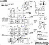
With BZLS volume at full level at CD pause, i have to put my head into the altec 828 horn flares for some very low level hum, and ear about 20 -30cm in front of the TD2001 horns for some hiss noise. With DAC power off i hear not less. All this without enclosure our groundplane still. The DAC needs at power up long time /40 seconds or so, until it delivers sensible sound. Before it makes some kinds of funny noises.
stefanobilliani,
I have looked at the I2S circuit and the reason I have stuck with the SPDIF is the transformers isolate you from CD player ground currents. If both the CDP and the DAC shared the command start ground the noise currents would be reduced ,however isolation is really the best way for me.
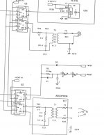
I ‘am attaching a jpg of my PS audio lambda CD transport output SPDIF. This interface was a major HF noise for my DAC, however I have resolved that. The problems were many.
1. Major ground bounce cause by the 74ACT logic this was switched to 74ALS. It slower but less noisy.
2. There an AC ground which connect of the SPDIF interface C215 that caused any AC noise to feed right to my DAC.
3. Removed older electrolytic and replaced them with OSCON low ESR caps.
4. Change the timing circuit to one my friend Jocko designed.
5. Got rid of some 74ACT04 that were distributing the clock, causing lot of noise currents.
6. The output drive of the SPDIF interface has a push pull action, generating a balanced clock signal. However, the 8414 or 12 only requires a single ended drive signal. I do plan to enhance both the RX and the TX still but for now I am just listening.
7. U3 was a 74ACT74 now change to ALS.
I have looked at the I2S circuit and the reason I have stuck with the SPDIF is the transformers isolate you from CD player ground currents. If both the CDP and the DAC shared the command start ground the noise currents would be reduced ,however isolation is really the best way for me.
I ‘am attaching a jpg of my PS audio lambda CD transport output SPDIF. This interface was a major HF noise for my DAC, however I have resolved that. The problems were many.
1. Major ground bounce cause by the 74ACT logic this was switched to 74ALS. It slower but less noisy.
2. There an AC ground which connect of the SPDIF interface C215 that caused any AC noise to feed right to my DAC.
3. Removed older electrolytic and replaced them with OSCON low ESR caps.
4. Change the timing circuit to one my friend Jocko designed.
5. Got rid of some 74ACT04 that were distributing the clock, causing lot of noise currents.
6. The output drive of the SPDIF interface has a push pull action, generating a balanced clock signal. However, the 8414 or 12 only requires a single ended drive signal. I do plan to enhance both the RX and the TX still but for now I am just listening.
7. U3 was a 74ACT74 now change to ALS.
Attachments
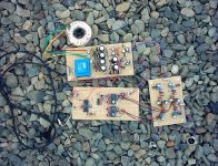
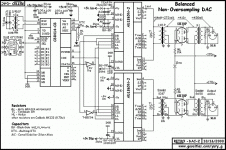
till said:No listening music, Vout from AD1865 driving 5m XLR cable to BZLS. The DACs first half is loosely based on http://www.geocities.com/yury_g/dac.htm,
Many thanks to jewilson.
till , it seems the url is not avaiable anymore , please can you post the schematic here if you have a copy or send it to me by e mail?
Thanks in advance.
and
looks that page does not like every kind of external link to it
pictures from http://www.geocities.com/yury_g/dac.htm
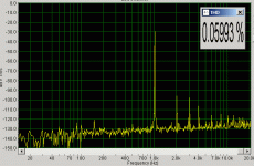
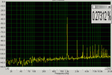
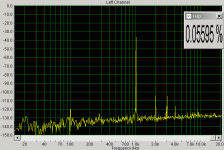
and as an experienced D1 builder: do you have any hint for me what would be the source of THD in one of my both stages?
looks that page does not like every kind of external link to it
pictures from http://www.geocities.com/yury_g/dac.htm
and as an experienced D1 builder: do you have any hint for me what would be the source of THD in one of my both stages?
Attachments
Till,
This is and instresting DAC, I not so much of a fan of the AD converters because I used the Burr Brown DAC's so many different times. Also, I don't like the idea of DAC with filters built into them.
One major things I do like are the sowder transformers, and there implementation. I also think it would be benifical to isolate the DAC from the preamp. The next DAC I build will have an output transformer to isolate it from the preamps noise.
I have found the ISO150AP it's a bi-directional digital coupler and it bandwidth up to 80 M baud.
http://focus.ti.com/docs/prod/folders/print/iso150.html
REPLACES HIGH-PERFORMANCE OPTOCOUPLERS
DATA RATE: 80M Baud, typ
LOW POWER CONSUMPTION:
25mW Per Channel, max
TWO CHANNELS, EACH BIDIRECTIONAL, PROGRAMMABLE BY USER
PARTIAL DISCHARGE TESTED: 2400Vrms
CREEPAGE DISTANCE OF 7.2mm
LOW COST PER CHANNEL
SO PACKAGE
APPLICATIONS
DIGITAL ISOLATION FOR A/D,D/A CONVERSION
ISOLATED UART INTERFACE
MULTIPLEXED DATA TRANSMISSION
ISOLATED PARALLEL TO SERIAL INTERFACE
TEST EQUIPMENT
MICROPROCESSOR SYSTEM INTERFACE
ISOLATED LINE RECEIVER
GROUND LOOP ELIMINATION
jewilson said:
I ‘am attaching a jpg of my PS audio lambda CD transport output SPDIF. This interface was a major HF noise for my DAC, however I have resolved that. The problems were many.
What a nice digital output!
Transformers, reclocking... that's the first time I see this
- Status
- This old topic is closed. If you want to reopen this topic, contact a moderator using the "Report Post" button.
- Home
- Source & Line
- Digital Source
- DAC alive