Dear Members......
For these 3 Linear Power Module MOD's (for the Oppo UDP-203) there are no detailed spec's available(at least I can't find them).
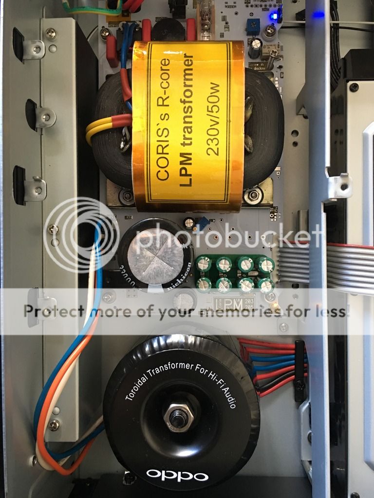
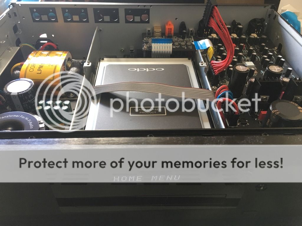
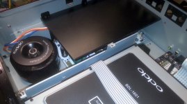
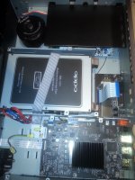
Is it possible, just on sight, to predict which of the 3 would produce the "cleanest" power. Two seems to have more, and a some "smaller", components on them. The other one has a bigger transformer and seems to have less components.
If I would buy one..... which one should I choose....
(price is not the issue here, just which one would gives the cleanest power)
Regards,
Jack
Option 1: picture 1,2,3,4
Option 2: picture 5,6
Option 3: picture 7,8
Care to post the web links?
100mH,2A? That'll be a HUGE inductor... Are you sure about the value?Easy upgrade for the 203 existing power supply.
Increase the value of the 2 of X caps in the AC line filter - must be X2 caps for safety. I fitted 1 uf between the chokes and 2.2 uf before it.
The electrolytics in the power supply aren't great quality - even though their marked 105 C
I used 10, 000 or 5,000 hour 105 C Panasonics for all of the following:
Main input cap increased from 68 to 150 Uf
Left the 47uf cap as 47 uf , but went to 63V
The 15 volt supply uses 4 of 470uf / 35v caps - i changed to 3300uf/25v , but theres only 14.5 volts on them, you might use the 4700 uf/16 volt caps
The 12 volt supply uses 3 of 1000uf/16v caps. Changed them to 4700uf /16 V
I used .1uf /63v Wima films under the board to bypass each of the 15 and 12 volt caps.
The inductors:
Theres two 3.3 mh/2A which I changed to 100 mh and fit in the same spot.
Theres a .1 mh/6A which i changed to 1 mh, but had to glue it on the board nearby and run new leads back to the holes. The new parts are taller so a little silicon goop for mechanical stability is advised.
Worked perfectly, I'm sure the full linear power supply replacement is better, but for $30 this is an inexpensive upgrade. And the caps will last longer.
Check you parts choice diameters before ordering, the ones I choose were the largest that would fit.
I have used the OPPOMod Power supply for the 105.
This looks similar so I can comment.
The standard model works well and is reliable, however it requires an AC voltage above 109 V or it will drop out.
For this reason, there is a special edition version of this power supply which uses Schottky diodes to reduce the drop out voltage.
The power supply is very clean, but does benefit from or require clean power.
Coris will probably tell you that his supply has better filtering of the incoming AC, etc. ,and so may be cleaner.
Last edited:

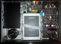
Received my order of Coris' LPM for 205 yesterday and found some time to install it today.
Build quality is superb! I'm not a technical guru but I managed to install it in about 1.5 hours, taking my time to make sure that it was done correctly.
Let the burn in fun begin! I'll report back with my impression after some burn in.
Build quality is superb! I'm not a technical guru but I managed to install it in about 1.5 hours, taking my time to make sure that it was done correctly.
Let the burn in fun begin! I'll report back with my impression after some burn in.
I can say now that the LPM approach is finished for my 205.
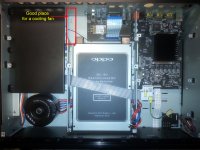
Accordingly to a pertinent observation, the transformer in this LPM it may be too close to the multi-channel board. As this linear type of PSU is not recommended to be covered (it need ventilation), even the original cover for former SMPS it may fit in its place, it should not be installed as it is.
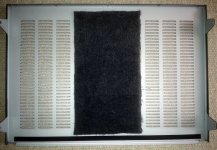
I appreciate as a good solution, the cutting of the lateral sides of the steel cover (without distorted its shape). You can see in the pictures hereby how it was done the steel cover processed, and the final result. Also, another steel plate could be used for the same dimensions, or even smaller, to cover only the transformer, and magnetically shield it against the multi-channel board above it.
I installed the original modified PSU cover using 2mm spacers on the original fixing places, so to have it a little bit higher.
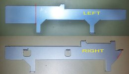
I found necessary that the bracket beside the optical driver (on the LPM side) to be cutted so as the pictures shows. This bracket modification it improve the LPM ventilation and it make the available space good and ready for placing a fan into it. This fan it will help a lot for the LPM ventilation, as for the “first floor” of the whole device too.
Next step it will be modifying the clock system, implementing my new version clock board, which is also modified mainly for the use of a smaller battery. The whole clock board it became smaller so, the smaller battery it charge faster; there is a better air circulation around it, and so on. The picture here it only illustrate the approach.
Accordingly to a pertinent observation, the transformer in this LPM it may be too close to the multi-channel board. As this linear type of PSU is not recommended to be covered (it need ventilation), even the original cover for former SMPS it may fit in its place, it should not be installed as it is.
I appreciate as a good solution, the cutting of the lateral sides of the steel cover (without distorted its shape). You can see in the pictures hereby how it was done the steel cover processed, and the final result. Also, another steel plate could be used for the same dimensions, or even smaller, to cover only the transformer, and magnetically shield it against the multi-channel board above it.
I installed the original modified PSU cover using 2mm spacers on the original fixing places, so to have it a little bit higher.
I found necessary that the bracket beside the optical driver (on the LPM side) to be cutted so as the pictures shows. This bracket modification it improve the LPM ventilation and it make the available space good and ready for placing a fan into it. This fan it will help a lot for the LPM ventilation, as for the “first floor” of the whole device too.
Next step it will be modifying the clock system, implementing my new version clock board, which is also modified mainly for the use of a smaller battery. The whole clock board it became smaller so, the smaller battery it charge faster; there is a better air circulation around it, and so on. The picture here it only illustrate the approach.
Attachments
Last edited:
Any photos of below the heat sink?I can say now that the LPM approach is finished for my 205.
Accordingly to a pertinent observation, the transformer in this LPM it may be too close to the multi-channel board. As this linear type of PSU is not recommended to be covered (it need ventilation), even the original cover for former SMPS it may fit in its place, it should not be installed as it is.
I appreciate as a good solution, the cutting of the lateral sides of the steel cover (without distorted its shape). You can see in the pictures hereby how it was done the steel cover processed, and the final result. Also, another steel plate could be used for the same dimensions, or even smaller, to cover only the transformer, and magnetically shield it against the multi-channel board above it.
I installed the original modified PSU cover using 2mm spacers on the original fixing places, so to have it a little bit higher.
I found necessary that the bracket beside the optical driver (on the LPM side) to be cutted so as the pictures shows. This bracket modification it improve the LPM ventilation and it make the available space good and ready for placing a fan into it. This fan it will help a lot for the LPM ventilation, as for the “first floor” of the whole device too.
Next step it will be modifying the clock system, implementing my new version clock board, which is also modified mainly for the use of a smaller battery. The whole clock board it became smaller so, the smaller battery it charge faster; there is a better air circulation around it, and so on. The picture here it only illustrate the approach.
I mean photos without the black heat radiator.Sorry, what you meant about heat sink?
")
Attachments
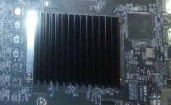
I see... I do not have such picture, as I did not removed this heatsink (yet). I had not so far the reason doing so. I must say that is not very easy to remove this heatsink, as it is soldered on the PCB. I could see that this heatsink it have thermal contact only with the processor, through a thermal pad. Not very good solution for best thermal transfer, but a convenient solution for the production line. My appreciation is that this section is not very important to focus on, at least in fist instances...
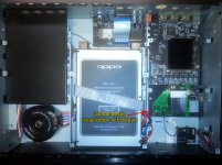
Well, the first step in modifying/improving the 205 model is finished now (I presume...), and it looks like in the picture hereby.
LPM in place, as the forced ventilation too. To create an efficient ventilation airflow, I covered the central perforations area of the cover, as you see in picture. So, the airflow is directed somehow by the fan, from the right side of the enclosure, to the left one, and out. For this approach to work properly, there is necessary cutting the chassis brackets as also shown in picture.
BTW, I still use the headphone out as line out, which it provide (in my appreciation) the best signal quality so far...
Attachments
Last edited:
Prepro replacement?
Hi, first post, I currently have a cheap bluray player attached to an older Integra avr with analogs out to a Sunfire amp. My goal is to replace the bluray and Integra with one of the new Oppo players and use it as a prepro as well as stream my bluray movies from a home built PC Windows server using Playon as the media server, 2 channel not important. My question is which one, from reading this thread it looks like a modified 203 might fit the bill for strictly multichannel use Or would a stock 205 be better? The other question is what type of mods would I need just for multi channel, the LPS is the obvious one, but what else would I need for movie streaming? Also, the Sunfire is connected to The Klipsch Ultra 2 Home Theater 7.1 speaker system. Please let me know if if I have left out any info that people would need to answer my questions. Thank you.
Hi, first post, I currently have a cheap bluray player attached to an older Integra avr with analogs out to a Sunfire amp. My goal is to replace the bluray and Integra with one of the new Oppo players and use it as a prepro as well as stream my bluray movies from a home built PC Windows server using Playon as the media server, 2 channel not important. My question is which one, from reading this thread it looks like a modified 203 might fit the bill for strictly multichannel use Or would a stock 205 be better? The other question is what type of mods would I need just for multi channel, the LPS is the obvious one, but what else would I need for movie streaming? Also, the Sunfire is connected to The Klipsch Ultra 2 Home Theater 7.1 speaker system. Please let me know if if I have left out any info that people would need to answer my questions. Thank you.
A stock 205 it will do it better on multi-channel, as it benefit of a dedicated (most advanced for moment) DAC. Also 205 it have improved audio over HDMI vs 203.
However, the first main mod/improvement in both cases (203/205) is the linear PSU (LPM) for digital stage. This it have an obvious positive impact over the quality of both sound and picture. Second improvement is the clock system, witch it differ a little bit for 203 and 205 models.
An interesting observation is that the improved analogue (stereo) audio stage in 203, it perform better than a stock 205, even thought the important price gap for the involved DAC chips (203 - AKM DAC; 205 - ESS9038Pro DAC). Here is mainly about the original design and implementation of the DAC chips in these two UDP Oppo models...
Thank you for the reply Coris. I will mainly using the analogs out to my Sunfire amplifier (tga-7201) which brings up a couple of questions. Would the analogs out on the 205 need any improvements? Also, I read in the avsforum that depending on the amplifier you are using the inputs have to have a certain impedance level to work correctly? If this true how do I know what that level is and if the Sunfire will work correctly with the 205 as a preamp?
In my opinion, the analogue stages of 205 it need improvements.
In general both the Oppo players outputs and the power amp inputs are designed to be compatible. Else you should consult the documentation for your amp and Oppo, regarding the outputs/inputs impedances for best fit.
My appreciation is that not in this field it may be the biggest problem, but in the way Oppo players it have being designed. So as it are these products (and for its prices) it may perform satisfactory for most of the users. This it not mean it can perform best, or are designed to perform best. It are actually quite far from such high end target. Improving these devices, it mean also an final price increasing as well...
Great information. Looking at the input inpedance for the Sunfire I see that the XLR is set at 10k ohms and the RCA inputs are set at 24k ohms. Not sure whether that is high enough or not but my thought is to get one of the Oppos and try it out. Then determine what and how much improvement I want to see and go from there.
Finally, I had the opportunity to take a closer look at the power system on stereo board of the 205. What I found? Not something very pleasant, I can say…
The positive regulator for opamps +/- power rails is a LM2940 (fixed 12v). The negative regulator is just an ordinary 7912… The toroïdal transformer it provide 2x14vAC for these +/- rails, which in DC it result (on load) 2x18v. Well, regulating from 18v to 12v, it mean that are at least 4v per rail, which it goes into the heat generation only… It could be enough 15v here to produce a well-regulated 12v, reducing so the heat generating… Not done it so, as Oppo designers may like the heat inside, or they does not know how to reduce it…
Most surprisingly is not this wrong energy balance of this section, but the ripple level, which is around 200mV at the regulators input… This is mainly because insufficient filtering capacity…The +/- 12v regulators outputs, are filtered by 1000µ…
The toroïdal transformer it deliver also 2x 6v AC, one for the stereo DAC power, and the second for multi-channel DAC power.
I have measured (on load) 6vAC before the rectifier bridge, and 6,3vDC after the bridge (filter cap – 3300µ/50v). Here is the big surprise! It have to be something quite wrong when a transformer it deliver 6v AC and in DC (after rectifying and filtering) one can find only 6,3v. There is obvious that the transformer it not fit with the necessary current required by the further circuits, and the filtering for these rails is very bad. There is a mystery how Oppo designers, have accepted a such wrong power approach for the analogue stage of a (advertised) high quality and performant model as UDP205. But this is not enough…
The ripple I have measured on this main 6,3V DC rail for stereo DAC power system is as high as 350mV! A very nice 100Hz saw shaped frequency over the DC power at the inputs of the “low noise” regulators for the DAC chip power rails… By the way, the 100Mhz oscillator which it clock the DAC, it is powered by the same 6,3v DC rail with this 350mV ripple on it… It is good so? NOT definitely!
I just started the extended improvement procedure for this stage…
Last edited:
- Home
- Source & Line
- Digital Source
- Oppo new UDP series players - 203/205 - Discussions, upgrades, modifications