I suppose you meant 205...
Well, I think to modify a little bit my old dividing approach. I want to use 108Mhz SAW as master clock. This frequency I will use it directly (as it is) to clock the DAC(s) chip(s). Then the divided frequency (to 27Mhz) I will use to clock the main processor. As the drive clock is 25Mhz, I`m force to use a stand alone oscillator for this clock. So, two oscillators in this case.
The three independent oscillators approach it still also be an option too, but I will prefer the above one, as more convenient. The three oscillators it mean one oscillator for DAC(s), one oscillator (divided to 27Mhz, or not) for main processor, and one oscillator for optical drive. I appreciate this last option as unnecessary complicated. As usually, simple the best (in my opinion).
For 203 model I think it is not necessary a such high frequency master clock (216Mhz), as 27Mhz it can be obtained from a 54Mhz SAW (current way of doing).
Last edited:
Yes, i was talking about 205
So, u use a 54mhz SAW for 203 master clock?
You've written (SAW oscillator for 27Mhz, and high quality TXCO for 25Mhz for your clock board)
Yes, for 203 model I use a SAW 54Mhz divided by 2, to get 27Mhz. As known, the SAW type oscillators are not produced for under 50Mhz frequency.
With just a few types of soldering tools, you can easily upgrade the quality of the analog audio output of Oppo UDP 203.
The Oppo UDP 203 uses an AK4458VN 8-channel DAC chip from Asahi Kasehi, Japan.
The chip is cheap for about 5 to 6 dollars, but sound quality is very natural and good. Because it is low price, it is also used for smart phone.
The DAC board of the Oppo UDP 203 has coupling capacitor. ELNA electrolytic capacitors (100uF/ 16v) are used.
Take out those electrolytic capacitors and change to 100uF OSCON together with Wima MKS2 1uF / 63V film capacitor a in parallel for the front left, right and subwoofer channels . Use 10 uF OSCON for other channels .
You can order Sanyo or Panasonic OSCOn from DigiKey Electronics - Electronic Components Distributor or Mouser Electronics - Electronic Components Distributor.
The substrate is marked with CE1,2,8,11,19,20,25,26.
If you want to play stereo music mostly, upgrade only the front left and right channels as shown in the picture below. If you want to surround channels, you have to change all 8 channels.
It is simple remodeling, but it will be rewarded with sure sound quality improvement.
Sound quality changes greatly with the material of the coupling capacitor.
One of the most preferred coupling capacitors in vacuum tube amplifiers costs 500$ for 0.47 uF and 600V of silver foil Mylar.
The role of the coupling capacitor is important. This is because the music signal flows through coupling capacitors directly while blocking direct currents.


very expensive coupling capacitor for Tube amps.

The Oppo UDP 203 uses an AK4458VN 8-channel DAC chip from Asahi Kasehi, Japan.
The chip is cheap for about 5 to 6 dollars, but sound quality is very natural and good. Because it is low price, it is also used for smart phone.
The DAC board of the Oppo UDP 203 has coupling capacitor. ELNA electrolytic capacitors (100uF/ 16v) are used.
Take out those electrolytic capacitors and change to 100uF OSCON together with Wima MKS2 1uF / 63V film capacitor a in parallel for the front left, right and subwoofer channels . Use 10 uF OSCON for other channels .
You can order Sanyo or Panasonic OSCOn from DigiKey Electronics - Electronic Components Distributor or Mouser Electronics - Electronic Components Distributor.
The substrate is marked with CE1,2,8,11,19,20,25,26.
If you want to play stereo music mostly, upgrade only the front left and right channels as shown in the picture below. If you want to surround channels, you have to change all 8 channels.
It is simple remodeling, but it will be rewarded with sure sound quality improvement.
Sound quality changes greatly with the material of the coupling capacitor.
One of the most preferred coupling capacitors in vacuum tube amplifiers costs 500$ for 0.47 uF and 600V of silver foil Mylar.
The role of the coupling capacitor is important. This is because the music signal flows through coupling capacitors directly while blocking direct currents.
very expensive coupling capacitor for Tube amps.
Gents, if only using the UDP as a transport i.e. digital out only, any reason to but the 205 over the 203?
If using the audio HDMI out as 'transport' - then 205 has the edge.
HDMI Audio Jitter Reduction
My appreciation is that a improved 203 (linear PSU for digital stage as a better clock system) it can very well compensate the design improvement for audio over HDMI in a stock 205.
The final prices in case of a improved 203 and a stock 205 it may be quite similar. At least a stock 205 it need to be improved for proper quality results., and in this scenario the final price is even higher, than for a 203.
In the design evolution of the Oppo players models over time, I could notice at least two very obvious efforts of the designers to improve the picture and sound quality of the devices, due to a high HF noise level into the digital stage/processing. This high level noise in digital system is mainly because the SMPS, used to power the system.
So instead to do something about the main high level HF noise source, by using a cheap SMPS, the Oppo designers chosen to add filters or sophisticated approaches, to get a better output result.
First they added the Darbee processor, which it filter and it "improve" the picture quality. Personally I do not appreciate the Darbee filter as an whatsoever improvement, but only opposite: an artificial and obvious processed video content.
Second improvement to overcome the high noise level into the players digital system is this last (also very good concept) jitter reduction for audio over HDMI. The fact that this mechanism it was added/introduced into the last 205 design, it mean that the high jitter on HDMI interface it was a issue indeed in all previous models.
So, Oppo designers had worked hard to add new circuits, filters and new stages into the digital system to overcome the high noise level issues, instead of doing something (simpler) to address the cause/sources of the problem: the SMPS, which it generate hundreds og mV HF noises in a very large spectre.
The digital system powered by a linear PSU it lower dramatically the overall noise level into the system, and it obviously improve the quality of the outputted content. This as a first level of an general improvement. Then it come the clock system upgrade, which it increase even more the quality of the processing.
Last edited:
My "DAC" is a Theta Digital Casablanca with Jitter Jail II so it already has a lot of immunity to HDMI jitter. I deployed a Jaehong Lee linear PSU (which is a relatively simple PSU design) for my Oppo 103 and I must admit I'm not really sure it made any difference. Agreed re Darbee.
Coris, are you offering upgrade solutions for the 203?
Coris, are you offering upgrade solutions for the 203?
Coris, are you offering upgrade solutions for the 203?
Yes, I do. You have an example for the last version of my full 203 upgrade in the post nr. 246.
In your case, using 203 only as digital transport, there are the linear PSU (LPM), and the clock system to be in place. Well, some other small improvements as well. Please PM for more details.
Last edited:
Improved ventilation 203
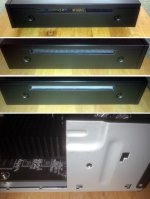
A solution for ventilation improvement in 203. Especially when the device is powered by a linear PSU. In addition to these windows in lateral sides of the enclosure, I use a fan inside, which it create a airflow from one to another of the cutted windows (admission right side, exhausting left side).
The windows are quite easy to be created, as the lateral sides are made of plastic. With adequate tools one can get a very aesthetically result. The metal chassis upper parts should be catted out, as shown in pictures.
Attachments
OPPO UDP 205 DAC circuits upgrade
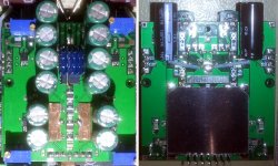
The main stereo balance and unbalanced output should be modified mainly.
In the figure, the yellow part shows the balanced output part and the unbalanced part are shown as the light blue.
The electrolytic capacitor is now used, they should be replaced with OSCON(SANYO or Panasonic) and Wima film capacitor ( MKS2 1uF/63V)

The second picture shows that only the unbalanced parts are connected in parallel with the Wima film capacitors. The balance part are marked in yellow.

Coupling capacitors are a very important part where the sound signal passes directly. The function is to cut off DC voltage and pass only music signal, which is very directly related to sound quality.
oscon in unbalanced portion

Wima film capacitors

The main stereo balance and unbalanced output should be modified mainly.
In the figure, the yellow part shows the balanced output part and the unbalanced part are shown as the light blue.
The electrolytic capacitor is now used, they should be replaced with OSCON(SANYO or Panasonic) and Wima film capacitor ( MKS2 1uF/63V)
The second picture shows that only the unbalanced parts are connected in parallel with the Wima film capacitors. The balance part are marked in yellow.
Coupling capacitors are a very important part where the sound signal passes directly. The function is to cut off DC voltage and pass only music signal, which is very directly related to sound quality.
oscon in unbalanced portion
Wima film capacitors
Improving analogue audio outputs for all Oppo models
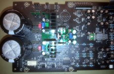
My new version fully differential XLR/RCA output module. Now with TPA6120 as buffer for RCA out. Ultra low noise regulators for each differential stage (OPA1632), with huge decoupling capacities.
My new version fully differential XLR/RCA output module. Now with TPA6120 as buffer for RCA out. Ultra low noise regulators for each differential stage (OPA1632), with huge decoupling capacities.
Attachments
Last edited:
Many people are interested in interconnection cable and power cable. Those are some times cost more than 1000$.
But most people overlooks the fuse.
Fuses are essential components that must be inserted to protect the device. the inside wire of fuse is thinner than the hair. If the current exceeds the rated current, it melts and breaks.
This is the biggest blind spot on the audio side. Even if you have a very thick power cable which dost more than 1000$, the electricity must pass through the fuse..
It might be like a car that ran on a 36-lane highway, which goes to narrow alleyway.
The fuses for audio are sold at high prices. such gold-plated fuses. cryogenic fuses, etc., it definitely makes a better sound than normal fuses.
However, the use of circuit breakers here has a definite positive effect.
A circuit breaker is made of a wide metal plate, which is in contact with the outside of the city, so electrical conductivity is a way different from fuse. When it is abnormal, it blocks the flow.
The cut-off time is fast enough to match the fuse, so you do not have to worry about protecting your device.
In the past, it was common to use large amperes for using at home, but from a few years ago there are also 1 to 3 A circuit breaker available for audio use. Since I applied it to the linear power supply of OPPO BDP players, for obvious effect, I removed the fuse from all my audio devices and changed it to a circuit breaker.
You can see a positive effect with resonable cost.
404 | DigiKey
It is available for purchase here. For source devices and pre amplifiers, buy 1.8 A to 2 A circuit breaker.
Use a 3 A class circuit breaker for power amp.
Mods Analogue Power system - 205
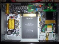
Well, finally I started the improvement process for the analogue power system on 205. Replaced the stock rectifier diodes with Schottky bridges. Replaced the +/- regulators, with an adjustable LM2991/41 regulators module, as added pre regulator module for DAC power rails.
Also first step in improving the clock system - soldering in place the UFL connector for stereo DAC new clock input...") .
.
Quite much more to be done further...
Well, finally I started the improvement process for the analogue power system on 205. Replaced the stock rectifier diodes with Schottky bridges. Replaced the +/- regulators, with an adjustable LM2991/41 regulators module, as added pre regulator module for DAC power rails.
Also first step in improving the clock system - soldering in place the UFL connector for stereo DAC new clock input...
.Quite much more to be done further...
Attachments
Last edited:
In these pics, are the wima caps added or a replacement? Also, should the balanced side have oscon as well? In your last pic, the wima at the far left appears to have one leg connected to the cap and one to the resistor. Is that correct? I'm asking because I have not looked at mine yet other than to install the new Oppo Mod LPM which I find to be fabulous.OPPO UDP 205 DAC circuits upgrade
The main stereo balance and unbalanced output should be modified mainly.
In the figure, the yellow part shows the balanced output part and the unbalanced part are shown as the light blue.
The electrolytic capacitor is now used, they should be replaced with OSCON(SANYO or Panasonic) and Wima film capacitor ( MKS2 1uF/63V)
The second picture shows that only the unbalanced parts are connected in parallel with the Wima film capacitors. The balance part are marked in yellow.
Coupling capacitors are a very important part where the sound signal passes directly. The function is to cut off DC voltage and pass only music signal, which is very directly related to sound quality.
oscon in unbalanced portion
Wima film capacitors
Thank you.Hi discopete.
Wima film cap should be added to OSCON in balanced output and unbalanced output.
The left part postion of balanced output is wrong positipned.
Sorry for this.
- Home
- Source & Line
- Digital Source
- Oppo new UDP series players - 203/205 - Discussions, upgrades, modifications