I GOT TO HAVE A SIGNAL POINT GROUND
Oli,
What you can do is to add jumpers to connect the ground together. Also, add extra hole for power so you’re lay out is flexible.
So when you find that your noise is to high you can disconnect the ground planes. Or if you find the noise is ok you can leave the jumpers in. This also allows to pick several different location on the PCB where you'd thinks the ground currents will cancel.
Re: A single ground plane!
Oli,
Yes, you understand it right. In the case of ADC or DAC chips: Think of the loop the currents run that have to pass the A/D or D/A barier. Induced voltages in that loop may work out quity nasty/.
The bottom line
- All gnd pins of all parts to 1 plane
- Reduce currents through plane by
- Reducing current amplitude and frequency content
- Reducing the common part of currents (i.e. place decoupling caps - aka decaps VERY close to the ground pins of the ICs)
- Place ICs interacting with RF signals close to each other (use common sense)
sp the plane will be near equi potential
succes
Oli said:To my horror I believe I am just understanding Guido's ground plane theory:
It's a single common analogue/digital ground plane!
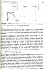
Splitting the ground plane creates a 'bottleneck' for return currents to flow through and often a long current path. This is especially true if current needs flow from one side of the split to the other side.
A single large ground plane will reduce the aforementioned bottleneck and reduce the loop size for return currents.
As long as the plane covers sufficient area any delicate ground inputs should not be affected by large return currents, since resulting potential drops will be minimal.
Guido, do I correctly understand it?
Does this mean all the grounds on my current design: PLL, DGND, AGND etc should form one continuous ground plane? e.g. Solder AGND and DGND pins of my CS8412 to the common ground plane?
Interesting stuff... I am having to rethink my ideas about that stuff we call electricity...

Oli,
Yes, you understand it right. In the case of ADC or DAC chips: Think of the loop the currents run that have to pass the A/D or D/A barier. Induced voltages in that loop may work out quity nasty/.
The bottom line
- All gnd pins of all parts to 1 plane
- Reduce currents through plane by
- Reducing current amplitude and frequency content
- Reducing the common part of currents (i.e. place decoupling caps - aka decaps VERY close to the ground pins of the ICs)
- Place ICs interacting with RF signals close to each other (use common sense)
sp the plane will be near equi potential
succes
Hi,
I think there is a misunderstanding regarding split ground planes. If one reads Analog Devices app note more carefully they do advocate puting complete ADC, DAC and clock source all on the same analog ground plane. You would use split plane only if digital part of the circuit is something like Pentium computer.
I have another question. I use SMD parts and double sided board. Because almost all of the connections are on the top side, top ground plane has many holes. Bottom ground plane is almost unbroken. Is there any advantage by stitching bottom and top ground plane with vias at regular interval (100-200mils) as oposed to placing vias only when there is discontinuity?
Second since board is fairly small, I can use thinner 0.8mm vs standard 1.6mm PCB. Would there be any advantage in that?
Best regards,
Jaka Racman
If you have to use one ground plane, it should be continuous. Havening the plane on the bottom connected via feed through is ok, but the plane has to be a continuous plane.
Still the optimum way of connecting mixed signal with precision converters is to use multiple continuous ground planes.
Still the optimum way of connecting mixed signal with precision converters is to use multiple continuous ground planes.
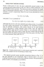
From my interpretation of the references shown in the last few postings, it would appear that in my application that using separate ground planes and hooking them up at a point of my choosing (the "star point") is preferable.
I guess Guido will disagree
and I am wondering what Jewilson will say about that.
Petter
I guess Guido will disagree
and I am wondering what Jewilson will say about that.
Petter
Fourier may give the reason for a single plane!

I believe Guido is trying to tell us that our digital 'square' waves are a Fourier summation of sine waves extending to infinately high frequencies. We should consider a simple audio DAC as a 'high frequency' circuit. In addition, spikes in the digital signal will further increase high frequency spectral content. A single plane is therefore preferred.
Is this right Guido?
Any further thoughts about my post #11: What power rating of resistor is appropriate to avoid initial inrush to the Os-Cons from destroying it. Can I get away with 0.125W, given the short pulse duration?
We should consider a simple audio DAC as a 'high frequency' circuit. In addition, spi
Oh, please stop, I told you how you could prove or disprove what Analog Devices, Bell Labs and Burr Brown are say regarding grounding and noise. You are not convincing me from what Guido stated, I done this for a living and it works.
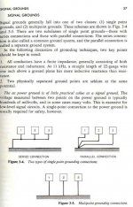
Find several points on your design and connect them with zero ohm resistors; however, you have to be able to provide power to the individual circuit’s planes areas.
Analog power should ground have its own return
Digital power ground should have its own return
Analog Signal ground should have its own return
In addition, if you keep using long run to from your supply and High Speed CMOS you are still going to have problems but not as bad, since the grounds are separate. However, your should build your circuit however you please.

Oli,
A 100uF capacitor holding 5V stores 2.75E-3 Joules. This is the worst case energy you have to transfer to the capacitor.
Now remembering that one Joule is 1W for 1 second, you will end up with .00275W being held by the capacitor.
Let's say that the current is constant over .1 second and assume the voltage is constant at half the 5V. My calculations indicate that your 10 Ohm resistor will dissipate 1mW in that time.
If we assume that the buildup takes place over .01 seconds, my estimates indicates resistor dissipation of .121W
This does of course exclude any power drawn by the load.
These estimates indicate there will not be a problem. The initial current will be maximum 5V/10 Ohm = .5A
This means that you will dissipate a maximum of 2.5W at that instant constantly reducing asymptotically as the voltage builds up. If you assume constant current of .5A
Allowing for errors and long circuit life I would put in at least a .5W but it is unlikely that you will have problems no matter what you go for.
Petter
(with a piece of paper, I would have done it with calculus )
)
A 100uF capacitor holding 5V stores 2.75E-3 Joules. This is the worst case energy you have to transfer to the capacitor.
Now remembering that one Joule is 1W for 1 second, you will end up with .00275W being held by the capacitor.
Let's say that the current is constant over .1 second and assume the voltage is constant at half the 5V. My calculations indicate that your 10 Ohm resistor will dissipate 1mW in that time.
If we assume that the buildup takes place over .01 seconds, my estimates indicates resistor dissipation of .121W
This does of course exclude any power drawn by the load.
These estimates indicate there will not be a problem. The initial current will be maximum 5V/10 Ohm = .5A
This means that you will dissipate a maximum of 2.5W at that instant constantly reducing asymptotically as the voltage builds up. If you assume constant current of .5A
Allowing for errors and long circuit life I would put in at least a .5W but it is unlikely that you will have problems no matter what you go for.
Petter
(with a piece of paper, I would have done it with calculus
Petter said:From my interpretation of the references shown in the last few postings, it would appear that in my application that using separate ground planes and hooking them up at a point of my choosing (the "star point") is preferable.
I guess Guido will disagree
and I am wondering what Jewilson will say about that.
Petter
Question 1
How, and which currents interact, e.g. run through that single point
Question 2: Do they run through the smallest loop possible
Question 3: How does the common mode impedance affect all currents
enjoy
Re: We should consider a simple audio DAC as a 'high frequency' circuit. In addition, spi
If oy understand the principle of local decoupling, and AC (RF) impedance towards the supply line, you'll notice it is not a problem to supply energy to the various circuits on the PCB. By doing so, you reduce the supply currents through the supply lines to virtual DC, hence that same DC runs through the ground plane.
Tube amps consisting of more stages use the same principle, for other reasons though.
Ciao
jewilson said:
however, you have to be able to provide power to the individual circuit’s planes areas.
Analog power should ground have its own return
Digital power ground should have its own return
Analog Signal ground should have its own return
In addition, if you keep using long run to from your supply and High Speed CMOS you are still going to have problems but not as bad, since the grounds are separate. However, your should build your circuit however you please.

If oy understand the principle of local decoupling, and AC (RF) impedance towards the supply line, you'll notice it is not a problem to supply energy to the various circuits on the PCB. By doing so, you reduce the supply currents through the supply lines to virtual DC, hence that same DC runs through the ground plane.
Tube amps consisting of more stages use the same principle, for other reasons though.
Ciao
Re: Fourier may give the reason for a single plane!
Hi Oli,
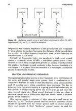
Yes, that is the point, we talk RF here. And for any current above a few kHz, the inductance of the grounplane is what counts. Withe the return (or mirror) current "far" away, each mm has about 1 nH inductance. For the return current more close (hence depending on the layout), something like 0.5 nH/mm can be taken.
Please note that thicker, or wider ground does NOT change its' impedance, only its' resistance.
Current through that impedance gives a voltage across the groundplane, which is in series with all signals refering to the plane
Ciao
Oli said:
I believe Guido is trying to tell us that our digital 'square' waves are a Fourier summation of sine waves extending to infinately high frequencies. We should consider a simple audio DAC as a 'high frequency' circuit. In addition, spikes in the digital signal will further increase high frequency spectral content. A single plane is therefore preferred.
Is this right Guido?
Hi Oli,
Yes, that is the point, we talk RF here. And for any current above a few kHz, the inductance of the grounplane is what counts. Withe the return (or mirror) current "far" away, each mm has about 1 nH inductance. For the return current more close (hence depending on the layout), something like 0.5 nH/mm can be taken.
Please note that thicker, or wider ground does NOT change its' impedance, only its' resistance.
Current through that impedance gives a voltage across the groundplane, which is in series with all signals refering to the plane
Ciao
- Status
- This old topic is closed. If you want to reopen this topic, contact a moderator using the "Report Post" button.
- Home
- Source & Line
- Digital Source
- Optimum Decoupling of Digital ICs
