Hi, I tried a few Squeezebox power supplies but I found they had some drawbacks in either the size, price or the HF/RF filtering department. Cheap chinese PSU boards on Ebay all lack something so it seems not many complete boards are out there. The Squeezebox needs a better PSU as the original SMPS does not give the best results.
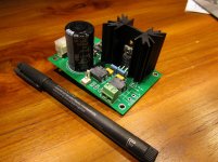
So I made this replacement linear very low drop low noise PSU that can deliver 5 V 3 A. It performs quite good although I am still testing and trying out stuff. Originally I started with a discrete design but quickly converted to recent regulator ICs. Some of those newer ICs had non optimal features and only 2 types remained. I leave it to you to check the picture which chip is being used")
Design goals were:
- must be a linear PSU
- low noise
- as compact as possible
- one board solution
- good HF/RF filtering both at input and output
- high reliability so "constant on" capable (please understand that I can not guarantee anything here)
- Low heat emission, low power loss i.e. as "green" as possible for a linear power supply
- rugged + overdimensioned
As a result it has adequate (IMHO) input and output CLC RF filtering which is not found on most replacement PSUs. Diodes are separate 5 A Schottky types, there are 2 output terminals for optimal cable routing and it has a green power LED (it won't accept blue LEDs just like me) as both a minimum load and as luxury item. I added pads for using an RC snubber circuit but haven't tried that myself yet. Either SMD or through hole resistors can be used for the voltage setting. Since I don't like modular designs it is a plain and simple one board solution. Just connect a 6 V transformer and output cabling and it is ready to be used. Testing is being done with special Rcore transformers that came on my way when the design started and at full load those are virtually silent + relatively cool and their stray field is low. I also use some O2 Joggler devices that can be connected to this PSU as well. As you can see it is quite compact, more compact than most replacement PSUs anyway. The idea is to cut off the cable of the original Squeezebox SMPS and connect it to this board.
I am posting this in the Digital Source section as I think it is the most appropriate section. Although being used to questions I will not respond to: "can I use a 24 V transformer that I have ?" and the like. The correct part values and types and the right transformer type will be in a BOM and that's it. I will spend considerable time in testing parts and discussion on the parts can be fun for you but not for me
Order form: link removed as GB has ended
GB will run till 1st of May.
So I made this replacement linear very low drop low noise PSU that can deliver 5 V 3 A. It performs quite good although I am still testing and trying out stuff. Originally I started with a discrete design but quickly converted to recent regulator ICs. Some of those newer ICs had non optimal features and only 2 types remained. I leave it to you to check the picture which chip is being used
Design goals were:
- must be a linear PSU
- low noise
- as compact as possible
- one board solution
- good HF/RF filtering both at input and output
- high reliability so "constant on" capable (please understand that I can not guarantee anything here)
- Low heat emission, low power loss i.e. as "green" as possible for a linear power supply
- rugged + overdimensioned
As a result it has adequate (IMHO) input and output CLC RF filtering which is not found on most replacement PSUs. Diodes are separate 5 A Schottky types, there are 2 output terminals for optimal cable routing and it has a green power LED (it won't accept blue LEDs just like me) as both a minimum load and as luxury item. I added pads for using an RC snubber circuit but haven't tried that myself yet. Either SMD or through hole resistors can be used for the voltage setting. Since I don't like modular designs it is a plain and simple one board solution. Just connect a 6 V transformer and output cabling and it is ready to be used. Testing is being done with special Rcore transformers that came on my way when the design started and at full load those are virtually silent + relatively cool and their stray field is low. I also use some O2 Joggler devices that can be connected to this PSU as well. As you can see it is quite compact, more compact than most replacement PSUs anyway. The idea is to cut off the cable of the original Squeezebox SMPS and connect it to this board.
I am posting this in the Digital Source section as I think it is the most appropriate section. Although being used to questions I will not respond to: "can I use a 24 V transformer that I have ?" and the like. The correct part values and types and the right transformer type will be in a BOM and that's it. I will spend considerable time in testing parts and discussion on the parts can be fun for you but not for me
Order form: link removed as GB has ended
GB will run till 1st of May.
Attachments
Last edited:
Hi, I tried a few Squeezebox power supplies but I found they had some drawbacks. I made this replacement linear low drop low noise PSU that can deliver 5V 3A. It performs quite good although I am still testing. I tried to make it as compact as possible. It has adequate input and output RF filtering IMHO.
Sign me up !
Let me first test this device some more. Since I have waited for months for the boards I could not be patient anymore and posted this somewhat prematurely in my enthusiasm. I made 3 versions for testing. The one on the picture is the first one, I made the others with larger heatsinks. Also various different tantalum caps are being tested.
Last edited:
What is a box ref ? No price known yet. As said: I made the mistake by posting this in my enthusiasm. I am still testing parts and measuring. As you know I want to deliver quality which costs time. This PSU should be best-of-class otherwise it won't have sense to build one IMO.
I don't have a Duet and I know nothing about them. It is kind of standard here not to bother with things you don't know. I have a Touch which is the reason i made a PSU for the Touch. If the Duet also likes 5 V DC at max. 3 A then it is fine, otherwise you are on your own. For those that need 8.7 V and have transformer that gives 110 V this project is not the right project. Please see post #1 for what the definitions are.
Checked my stock and I think I can make 20 sets of PCBs complete with a Rcore transformer for European builders. That is if there are any guys that want to build one Shipping costs and difficulties prohibit from sending out of Europe. But first testing and when everything is OK a GB can be discussed.
I don't have a Duet and I know nothing about them. It is kind of standard here not to bother with things you don't know. I have a Touch which is the reason i made a PSU for the Touch. If the Duet also likes 5 V DC at max. 3 A then it is fine, otherwise you are on your own. For those that need 8.7 V and have transformer that gives 110 V this project is not the right project. Please see post #1 for what the definitions are.
Checked my stock and I think I can make 20 sets of PCBs complete with a Rcore transformer for European builders. That is if there are any guys that want to build one
Shipping costs and difficulties prohibit from sending out of Europe. But first testing and when everything is OK a GB can be discussed.
Last edited:
Pardon, my french ! I meaned : case-box (cabinet; housing) reference on Mouser/Digikey/Farnell/R-S (e.g. Hammon number xxxx and an alternative one...oups 2 BOM = too much choice and confusion ) to cloth the cute board...
 But like the Squeeze-Box Duet (9V) it was a second degree joke, sort of private joke for you because your advert about caps mods and time spent for optimisation. Life is too short for sense of humour
you may have right ! I'm sure this PSU is good enough ,thank you... great.
(not second degree)Did you benchmark it both with scopes and ears with the one maid for the Subbu as well. Noise floor is lower ? (not second degree questions!).
Saw Subbu bought 2 Distinction-1541 boards
... do you have also some others PSU for our special Squeeze Box which needs also - 5 V and -16V (second degree question) ?regards....
Syntax error, input overload.....it seems better just to wait and see what comes Eldam. It is not a dictate and change project, think of a diode please
I don't agree life is too short for humor, on the contrary ! Life is too short for waisting time. So please see post #1 to know what this PSU does. If you need something else then please look elsewhere.
I don't agree life is too short for humor, on the contrary ! Life is too short for waisting time. So please see post #1 to know what this PSU does. If you need something else then please look elsewhere.
Last edited:
The Squeezebox needs a better PSU as the original SMPS does not give the best results.
So what problems did you find with the original supply, and how much improvement do you get with the linear supply?
Hi JP,
As I said, it is good as it is ! Good enough is good enough, and personal cursor level is personal cursor level, people are free to mods and cominicate with no offense to the designer. Sorry for diodes, not dictate way of communication to me... nore from me ! Btw, readed your advertisement about mods, caps, etc !
Was just sense of humour and also to overlight your off the shelf diy no dictate project... As I understood french humour is different than Dutch your one)) I putted above selfies and explanations in () !
PS: prefer the resistor (can travel in the two sens) instead diode! resistor is said resistance in french also... ahhh the French Resistance... always bad litterature in France !
Thanks for sharing, regards
Eldam
As I said, it is good as it is ! Good enough is good enough, and personal cursor level is personal cursor level, people are free to mods and cominicate with no offense to the designer. Sorry for diodes, not dictate way of communication to me... nore from me ! Btw, readed your advertisement about mods, caps, etc !
Was just sense of humour and also to overlight your off the shelf diy no dictate project... As I understood french humour is different than Dutch your one
)) I putted above selfies and explanations in () ! PS: prefer the resistor (can travel in the two sens) instead diode! resistor is said resistance in french also... ahhh the French Resistance
... always bad litterature in France !Thanks for sharing, regards
Eldam
So what problems did you find with the original supply, and how much improvement do you get with the linear supply?
Not problems, the original power supply just works OK and it probably will for quite some time. If there were safety or reliablity problems Logitech would have them replaced I guess.
However, the original power supply does not give a very clean voltage and the design goals were likely to add a cheap adapter with the device to keep costs down. SMPS are popular for some reasons and cost surely is one of them. The Touch also feeds a little noise into its own power supply. I tried to remedy both issues which leads to better results. There are quite some companies that make replacement supplies for the same reason (apart from making money which is their main goal). I tried out quite some power supplies, both switching and linear ones. Best results were with linear power supplies but IMO they all lack one or more of the aforementioned features. The ones I liked best were quite bulky and they developed heat which is something I don't like when I am away from home.
When I added a cap directly on the supply lines in one of my Touch devices it was clear that the power supply needs to be improved as there is not much space in the Touch for better filtering/decoupling. I recently found small enough polymer caps to try out in the device itself but to be honest working in the device is not something everybody will want to do.
Last edited:
Member
Joined 2006
I tried out quite some power supplies, both switching and linear ones. Best results were with linear power supplies but IMO they all lack one or more of the aforementioned features.
Did you measure how much improvement you achieved?
Indeed, seems a bit pointless to have a small, lightweight player that needs to be fed by a much larger and heavier power supplyThe ones I liked best were quite bulky and they developed heat which is something I don't like when I am away from home.
Was it a small-ish filter/bypass cap, or a large electrolytic one?When I added a cap directly on the supply lines in one of my Touch devices it was clear that the power supply needs to be improved as there is not much space in the Touch for better filtering/decoupling.
In previous posts I indicated clearly in what stadium progress is. I will not post my numbers. It is better when a third party measures and it seems something like that will take place. IMO it is obvious anything I say about my own design is to be taken with a grain of salt. At least that is how people generally feel about such matters.
I know the Swenson PSU but I wanted output filtering as well. IMO the PSU needs better filtering and also LT1084 is not the best chip for this purpose. All matters of technical taste and preference. Since not many make a device like this I just had to make my own. As before I think it is nice to have others try and enjoy the thing too just like with our Subbu V3 DAC. It makes no sense to have just 2 PCBs produced.
edit: i just realized that I spent more time in posting in this thread than it takes to finish one of the PSUs I am back to the case work as I learned that many builders need to see a working completely built example. Give it some weeks and we'll see how things develop.
I know the Swenson PSU but I wanted output filtering as well. IMO the PSU needs better filtering and also LT1084 is not the best chip for this purpose. All matters of technical taste and preference. Since not many make a device like this I just had to make my own. As before I think it is nice to have others try and enjoy the thing too just like with our Subbu V3 DAC. It makes no sense to have just 2 PCBs produced.
edit: i just realized that I spent more time in posting in this thread than it takes to finish one of the PSUs
I am back to the case work as I learned that many builders need to see a working completely built example. Give it some weeks and we'll see how things develop.
Last edited:
In previous posts I indicated clearly in what stadium progress is. I will not post my numbers. It is better when a third party measures and it seems something like that will take place. IMO it is obvious anything I say about my own design is to be taken with a grain of salt. At least that is how people generally feel about such matters.
I am pretty sure people approve of actual measurements, noise spectrum shots etc., and I wasn't asking only about your design, but also the other ones (both switching and linear ones) you had tried.
You just want to know too much I feel like being tested for an exam. I also don't care about what other approve or not as it is my thread. My experience is the more people know the more questions they have and the less time I can spend making stuff.
Since I knew I wanted something that can not be found for a reasonable price I knew beforehand it would have to be something I made myself. The only one I measured thoroughly was a dutch commercial product of which I still have one as it performs OK. It is not DIY though but that is not the products fault. All logic aside, I just wanted to make a very good PSU for the Touch as I really like the device. OK, I love the device. For a small sum of money it is possible to get more out of the Touch. No more no less.
I feel like being tested for an exam. I also don't care about what other approve or not as it is my thread. My experience is the more people know the more questions they have and the less time I can spend making stuff.Since I knew I wanted something that can not be found for a reasonable price I knew beforehand it would have to be something I made myself. The only one I measured thoroughly was a dutch commercial product of which I still have one as it performs OK. It is not DIY though but that is not the products fault. All logic aside, I just wanted to make a very good PSU for the Touch as I really like the device. OK, I love the device. For a small sum of money it is possible to get more out of the Touch. No more no less.
Last edited:
You just want to know too much
Definitely don't want it to seem like an exam - I am just curious, but a lifetime in technology and engineering has made me fact- and evidence-based. Too much anecdotes and folklore out there!
I am also used to submitting not only my designs, but also my assumptions and reasoning for peer review - a hundred sets of eyeballs and brains are always better then just one set.
Fair enough.Since I knew I wanted something that can not be found for a reasonable price I knew beforehand it would have to be something I made myself.
That is the part that will keep me asking questions - all too often things that should be an improvement turn out not to be. I do feel it is important to verify results.For a small sum of money it is possible to get more out of the Touch. No more no less.
a hundred sets of eyeballs and brains are always better then just one set.
Although the logic does not escape me at all I am not so sure anymore about that with regards to PSU's for the Touch. Just google and check what commercial PSU contraptions there are on the market. Not being the bragging type but I think the SBT PSU (as it is called) is a little unique FWIW even while it is just a simple old fashioned linear PSU with some twists.
Last edited:
I am not so sure about that. Just google and check what commercial PSU contraptions there are on the market.
Sure - lots of cheap crap out there. But that is also a problem with commercial designs - they are *not* checked by hundreds of eyeballs and brains.
The reason a lot of open source software is actually better than proprietary stuff is exactly the open peer review process. And I see the DIY community as a hardware equivalent of open source. We share our ideas and designs - but also learn what we got wrong.
This is no open source thing as it is my device and I am not asking for ideas. The only way to check and know how it performs at this stage is when you tell me you want to be a beta tester. Not just talk but real soldering and measuring! You are then free to post whatever you conclude from your own eyeballs/brains/measurements. That would be way less tiring than commenting to and fro as it already costs too much time.
Ready for the challenge ? Then send me a PM. Please tell me you have a Touch as I can't and don't want to send you one
Ready for the challenge ? Then send me a PM. Please tell me you have a Touch as I can't and don't want to send you one
Last edited:
- Status
- This old topic is closed. If you want to reopen this topic, contact a moderator using the "Report Post" button.
- Home
- Group Buys
- Squeezebox Touch PSU