No, I'm using a nano with your latest sketch (unmodified yet), connected as described. The mods are:
1. 78L05 to TVDD (failure with reverse pinout, be aware of SOT89!!!) One chip and one bridge on the bottom of the board, inductor #3 removed;
2. LT1963, and that 78L05 moved from analog cap to digital (one track cut, one bridge);
3. Int0 wired to the free pin of 4-pin header;
4. Discrete linear regulator for the DACs (not yet installed, will do after SRC debug).
That's all mods for now.
Thank you for help. Nearest plans - ignore int0 and try polling the chip. Voltages are ok now, so the chip is at least not burnt short. No activity on i2s bus, the data pins appear to be in Z.
Why 4397. One of my pals is an old monster in audio, and has told me that nothing in AKM assortment can bear with 4397 in parallel; considering that it's a comparatively rare chip, used mainly in hiend devices, I took the risk... and a couple chips from his stock.") We're diyers and always open for challenge, huh?
We're diyers and always open for challenge, huh?
1. 78L05 to TVDD (failure with reverse pinout, be aware of SOT89!!!) One chip and one bridge on the bottom of the board, inductor #3 removed;
2. LT1963, and that 78L05 moved from analog cap to digital (one track cut, one bridge);
3. Int0 wired to the free pin of 4-pin header;
4. Discrete linear regulator for the DACs (not yet installed, will do after SRC debug).
That's all mods for now.
Thank you for help. Nearest plans - ignore int0 and try polling the chip. Voltages are ok now, so the chip is at least not burnt short. No activity on i2s bus, the data pins appear to be in Z.
Why 4397. One of my pals is an old monster in audio, and has told me that nothing in AKM assortment can bear with 4397 in parallel; considering that it's a comparatively rare chip, used mainly in hiend devices, I took the risk... and a couple chips from his stock.
We're diyers and always open for challenge, huh? First of all: The Nano software wasn't tested on AK4118 board, but maybe somebody subscribed to this thread has implemented it, I don't remember. I changed latest software of AK4118 version because I forgot to check a register, but I can't test the result.
In general, the software checks for INT0 pin to become HIGH, which means either unlock or sample rate change. So when locked, INT0 pin is LOW. When locked to a signal, it must also be valid or else no audio output either (dacs are kept in reset state, i2s should be output). To determine validity of signal, the controller needs to read fs from AK4118. So check the 4 SPI lines MISO, MOSI, CLK, CS.
Also, when using AK4397, you need to set 00H register ACKS bit to 1. This enables automatic MCK speed selection, default on AK4399.
Got the lock on the coax input! It's just been a cabling error, so Nino's software looks fine.
No sound on toslink, but I'm still feeding the torx with 3.3v from LT1963, so it may not work at all, I haven't seen 3v torx yet. Will route the voltage for it from somewhere else, later.
Now - power and filters for the DACs. Stay tuned.
Meanwhile, I'm open for ideas about merging channels. Honestly, I was away from FPGAs since early 90's, so it's proper to say that I know nothing now. I have an Altera EPM240 dev board and some desire to explore the functions of it, but it'll take a lot of time to write the multi-bitrate i2s splitter. Or should I simply cross-patch the DACS, left to left, right to right, provided they're voltage output, not current output devices?..
pca01: Thanks for sharing pictures!
megaymir: Welcome to the thread. In what way did the sound of the DAC improve when diodes were swapped to BYV27? They are fast recovery, as well as Schottkys.
If you're looking for a good mod for this dac, I would recommend to do the TVDD mod first.
Nino[/QUOTE
It is not easy to describe in a foreign language, but the change is beyond the usual "dynamic" "clear" "fast" "bright" "soundstage" tags. It became something more open, but deeper a litle bit. I'd say, the experience factor, the "aha" or "okey" feeling improved.
Schottky diodes generates wide bandwidth noise in general, maybe this thing has something to do with BYV's Controlled Avalanche Characteristic feature.
I go for the other mod's, ordered some resistors for the opamp stage, all caps on the board will be changed one by one, except the big filters, which are Nichicon KG.
I just turned on the solder station to switch the zeners for the analogue psu. Low noise types will be used. Considering to use two-two lm329 in series.
I have the DAC7 with dual WM8741 in original condition, it sounds very - very good. I think I’ll keep it as it is to have a reference, because now the two DAC with the same type of opamps sounds more or less the same, differences are little.
Anyone here into CPLD/FPGA?
I suggest that cross-paralleling 2 chips with separate grounds will sound no better than proper I2S splitted into 2 separate output stages. Of course I understand that I'm the only enthusiast here (yet) to try paralleling 4397's - BUT if we get a FPGA implemented, we could have also a free I2S switch: say, a proper 32-bit/DSD xmos module could be connected in a blink.
Uhm?
Hi cu6apum,Anyone here into CPLD/FPGA?
...
Tempting...(no experience with it) but for now an i2s switch isn't what I need. I'm going to try the I2SoverUSB board (JLSounds) on this 2xAK4399 DAC first with sp/dif output. This way I can still make use of the Arduino controller. If I want to feed the DAC i2s directly, I have a problem when I want to use the sp/dif receiver too. But first I want to know if the i2s approach offers significantly better SQ in my current DAC setup, and maybe I'll choose to disable sp/dif inputs all together (I'm planning a DAC with LAN input).
I think you're probably right that splitting the i2s in left/right is the only way to parallel AK4397 properly.
Nino,
first of all, I've been dealing a LOT with Luben's I2SoverUSB. It's a great device that I'm using as a part of my ES9018 top-end dac design. I highly recommend it exactly in i2s/dsd modes, that's what I'm planning with AKM thingy, if I finally get this thingy working...
Because I have AK4118 failed again!!! No further changes were made, but it quit responding. I just finished the linear power for the dacs, and the filter part. Is it THAT sensitive to esd that I've occassionaly stroke a lightning to it?! I made way more tortures to the Sabre chip, but it keeps singing.
Thinking now of cutting out that 4118 and feeding i2s directly from my USB module. But a lot of people keep using archaic spdif, something's to be done about it anyway.
UPD. What I've checked already, in case you join the investigation... TVdd is 4.98V, DVcc+AVcc = 3.3V, all the legs connected properly. Upon init, PDN drops for several seconds, CLK and MOSI flash a bit, MISO is standing high. If I cut the pull-up resistor from it, MISO gets low, and the controller shows 44.1k lock eternally. Looks like MISO is in Z...
Last edited:
Eventually it isn't. Tomorrow will try to figure why. It's looking like Z; if I touch the scope probe set on this pin, the screen shows 50Hz flicker up from 0V. If I don't, it keeps low. With resistor, it sticks to high. Yesterday it did work with the resistor: I cracked my brain today, but found nothing yet.
Yes, you're right, I was mistaken, I confused it with INT0 pin. But better remove the pull-up. The MISO line stays high Z, except the second half of a read sequence, then the MISO line transfers data to the controller. The lock/unlock display mechanism is triggered on INT0 pin state change only.
Output stage
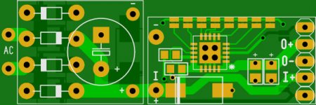
I have finished the PCB layout of the DAC output stage (aka Lynx 60). I have only replace two LME49710 with one LME49720. The PCB size is 47,5mm x 27mm. It has 4 layers.
I have already ordered it here: PCB Prototype Manufacture Service 2-Layer 0.16-3.84 inches2 10pcs | eBay
In addition to this PCB I have make the 2 layers layout of a small power supply module. It’s based on this LDO regulator: http://www.diyaudio.com/forums/vendors-bazaar/263618-tps7a4700-low-noise-ldo-regulator-pcb-8.html . It can be used with or without rectifier, even as the direct replacement of any LM78XX regulator. The size of this PCB is 47mm x 15,6mm.
After I receive PCBs (I hope, it will be finished in 1 month) and test it, I can share both layouts.
I have finished the PCB layout of the DAC output stage (aka Lynx 60). I have only replace two LME49710 with one LME49720. The PCB size is 47,5mm x 27mm. It has 4 layers.
I have already ordered it here: PCB Prototype Manufacture Service 2-Layer 0.16-3.84 inches2 10pcs | eBay
In addition to this PCB I have make the 2 layers layout of a small power supply module. It’s based on this LDO regulator: http://www.diyaudio.com/forums/vendors-bazaar/263618-tps7a4700-low-noise-ldo-regulator-pcb-8.html . It can be used with or without rectifier, even as the direct replacement of any LM78XX regulator. The size of this PCB is 47mm x 15,6mm.
After I receive PCBs (I hope, it will be finished in 1 month
) and test it, I can share both layouts.Attachments
Last edited:
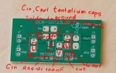
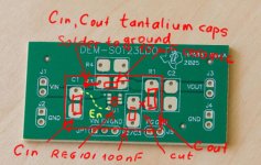
You' re welcome. For "big" tantalium caps you may need to create a small solder plate under original plates.Can you post the schematic?
Attachments
Last edited:
- Status
- This old topic is closed. If you want to reopen this topic, contact a moderator using the "Report Post" button.
- Home
- Source & Line
- Digital Line Level
- ebay:Weiliang Dual X2 AK4399 DAC with LCD