After several prototypes I am wondering what the best path would be.
Load the PCM63 with a 10 Ohm resistor and add 10X extra amplification behind it?
Or...stick with the max 100 Ohm and leave the amplification behind in 10x lower?
I know the data/measurements for values above 100Ohms, but is there also data (or blind listening tests) for values below 100 Ohm?
Load the PCM63 with a 10 Ohm resistor and add 10X extra amplification behind it?
Or...stick with the max 100 Ohm and leave the amplification behind in 10x lower?
I know the data/measurements for values above 100Ohms, but is there also data (or blind listening tests) for values below 100 Ohm?
69 people looking...so better put some answers here 
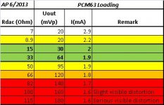
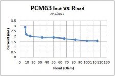
Well, with the LL1636 attached (no secundary load), I varied the Prim resistor values at the DAC side and measured the peak-voltage at the DAC-output with a scope.
It appears that the DAC current source has it's stable region with a load of 15...50 Ohms
Well, with the LL1636 attached (no secundary load), I varied the Prim resistor values at the DAC side and measured the peak-voltage at the DAC-output with a scope.
It appears that the DAC current source has it's stable region with a load of 15...50 Ohms
Attachments
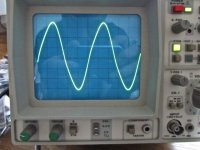
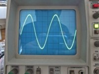
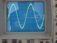
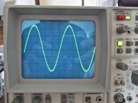
20Hz Different loads, signal behind the I/V transformer. Sine signal distorts at high Rdac (68 Ohm).
This is either caused by the current source of the DAC, not having enough internal voltage to provide sufficient current....or the higher voltage of the input I/V transformer when using the higher Rload causes the transformer to saturate (?No?). Could be verified with a CD having 20Hz signal at 0dB, -10dB, -20dB, -30dB etc...
The 68 Ohm load causes a clear deformation of the signal:
Attachments
20Hz Different loads, signal behind the I/V transformer. Sine signal distorts at high Rdac (68 Ohm).
This is either caused by the current source of the DAC, not having enough internal voltage to provide sufficient current....or the higher voltage of the input I/V transformer when using the higher Rload causes the transformer to saturate (?No?). Could be verified with a CD having 20Hz signal at 0dB, -10dB, -20dB, -30dB etc...
The 68 Ohm load causes a clear deformation of the signal:
try the same measurements and test, only this time leave pin 5 floating....
Boky
try the same measurements and test, only this time leave pin 5 floating....
Boky
Did that, even THD was the same..
You are measuring transformer rather than dac here
transformer is reactive component with 20zHz You exploring more trafo against the
dac which is in this set up a generator.
.
If You are willing please try to measure same bur without trafo?
.
I am interested because I am almost to finish my classic dac with 4 x PCM63PK per channel
.
transformer is reactive component with 20zHz You exploring more trafo against the
dac which is in this set up a generator.
.
If You are willing please try to measure same bur without trafo?
.
I am interested because I am almost to finish my classic dac with 4 x PCM63PK per channel
.
BTW BPO pin can be left NC
or connected to ground or via some current source of 2mA to -V.
In this case the Iout swings from 0 to 4mA
Giving the only "negative" voltage @ Riv phase shift of 180deg.
While BPO is not consuming the 2mA and like in original topology it goes from -2mA to 2mA? This leeds out that @ Riv will have phase of 0deg when Iout have negative mark,
to 180deg when it is positive.
.
I am not sure what will I do?
probably I will usee this value like some Vref for the external IV circuit?
20Hz Different loads, signal behind the I/V transformer. Sine signal distorts at high Rdac (68 Ohm).
This is either caused by the current source of the DAC, not having enough internal voltage to provide sufficient current....or the higher voltage of the input I/V transformer when using the higher Rload causes the transformer to saturate (?No?).
Did you connect the primary between pin 6 and ground, or between 6 and 4? Or thorugh a capacitor?
If you don't take care of the DC-offset then that will saturate your transformer.
You are measuring transformer rather than dac here
transformer is reactive component with 20zHz You exploring more trafo against the
dac which is in this set up a generator.
.
If You are willing please try to measure same bur without trafo?
.
I am interested because I am almost to finish my classic dac with 4 x PCM63PK per channel
.
Measuring without the transformer...the signal will be too low.
I expect that what I see is the transformer as load and the DAC-output can not handle it with high Rdac....so not the actual transforming function causing this....
With a low Rdac it seems the DAC will "see" less induction in total
But still....when loading a DAC with a transformer and Rdac...this is likely the effect you will encounter
BTW BPO pin can be left NC
or connected to ground or via some current source of 2mA to -V.
In this case the Iout swings from 0 to 4mA
Giving the only "negative" voltage @ Riv phase shift of 180deg.
While BPO is not consuming the 2mA and like in original topology it goes from -2mA to 2mA? This leeds out that @ Riv will have phase of 0deg when Iout have negative mark,
to 180deg when it is positive.
.
I am not sure what will I do?
probably I will usee this value like some Vref for the external IV circuit?
What will it bring??? I measured with/without having 5+6 connected no difference...
How large would the input impedance of a typical opamp current-to-voltage converter be?
0 Ohm (virtual GND)
Did you connect the primary between pin 6 and ground, or between 6 and 4? Or thorugh a capacitor?
If you don't take care of the DC-offset then that will saturate your transformer.
5+6(+) and 7(GND)
Not to toot my own horn, but I built a PCM63 based DAC with a resistor IV stage back in the mid 90's. (See: http://quadesl.com/pdf/tube_dac.pdf or SDS Labs DAC Designs) I did a bunch of tests with different IV resistors, and I settled on 100 ohms as being a large enough signal to not degrade the SNR too much, but still kept the output pin away from the clamping diodes and the clipping they would cause. It's been a lot of years, and I don't have my test data on that anymore, but a lot of people have built my design (I used to sell circuit boards for it), or have built similar passive IV stages with the PCM63, and I've not heard any issues with a shunt resistor in the 100 ohm range.
Sheldon
Sheldon
Not to toot my own horn, but I built a PCM63 based DAC with a resistor IV stage back in the mid 90's. (See: http://quadesl.com/pdf/tube_dac.pdf or SDS Labs DAC Designs) I did a bunch of tests with different IV resistors, and I settled on 100 ohms as being a large enough signal to not degrade the SNR too much, but still kept the output pin away from the clamping diodes and the clipping they would cause. It's been a lot of years, and I don't have my test data on that anymore, but a lot of people have built my design (I used to sell circuit boards for it), or have built similar passive IV stages with the PCM63, and I've not heard any issues with a shunt resistor in the 100 ohm range.
Sheldon
Hi Sheldon,
Your design has been on my shelf as inspiration to start my project. Nevertheless I think it will also depend on what system a concept is evaluated (or measured)...in my case all the minor differences are significant to say the least
Hi Sheldon,
I think I should mention one crucial difference in design though that might have an significant effect of Rdac loading. Mine uses an I/V transformer and the Rdac will make the DAC load less inductive...and in your case the DAC will always see a nice resistance (not fighting the DAC)...
So low values in my case will make "forget" the DAC there's actually a coil attached as well
Reg
Arno
Just to share our experience though it is with the PCM1704 using transformer I/V, (Lundhal 1674). Our "gang" of users independently settled on an I/V resistor of between 540 and 490ohms. We have tried using lower resistance (right down to 195ohms) and while this seemed to boost the bass reproduction, we felt that the sonics became compressed. Of course there is also the issue of decreasing gain with smaller value resistors.
Just to share our experience though it is with the PCM1704 using transformer I/V, (Lundhal 1674). Our "gang" of users independently settled on an I/V resistor of between 540 and 490ohms. We have tried using lower resistance (right down to 195ohms) and while this seemed to boost the bass reproduction, we felt that the sonics became compressed. Of course there is also the issue of decreasing gain with smaller value resistors.
That's a VERY high value. Would be interested how the sine signal at 20Hz 0dB looks (or measures on THD)...got any data on this?
I would expect that the DAC output sees more of the inductive part as load (which is the case with a high value resistor) and if the current source in the DAC can not keep the current steady enough during the long stretch in a low F signal, there will be generated a voltage in the coil that "fights" the drive-current change of the DAC (V = - L (dI/dt), if dI/dt changes the fight begin...no? )....and That's what I think I saw in the deformed wave shapes.
So...actually...I am looking forward to move to 10 Ohm...or perhaps 5Ohm...
Last edited:
- Status
- This old topic is closed. If you want to reopen this topic, contact a moderator using the "Report Post" button.
- Home
- Source & Line
- Digital Source
- PCM63 resistor Value