That's a VERY high value. Would be interested how the sine signal at 20Hz 0dB looks (or measures on THD)...got any data on this?
I would expect that the DAC output sees more of the inductive part as load (which is the case with a high value resistor) and if the current source in the DAC can not keep the current steady enough during the long stretch in a low F signal, there will be generated a voltage in the coil that "fights" the drive-current change of the DAC (V = - L (dI/dt), if dI/dt changes the fight begin...no? )....and That's what I think I saw in the deformed wave shapes.
So...actually...I am looking forward to move to 10 Ohm...or perhaps 5Ohm...
have you tried a good current feedback OP as I/V? Dynamic impedance can easily go to below 1 ohm with AD811.
Boky
have you tried a good current feedback OP as I/V? Dynamic impedance can easily go to below 1 ohm with AD811.
Boky
 That is exactly where I wanted to get away from. WI
ith an OP it's technically easy and sonically the lesser option for me.
but of course.... 811 is quite easy to implement.
Boky
Last edited:
I implemented many high-speed OP's and usually the challenge is to keep the "calm" and avoid oscillations. Compare the internal design of the opamp and the number of components to a single tube-stage and a hand full of discrete components and it's clear which one fits best in the less is more philosophy
That's a VERY high value. Would be interested how the sine signal at 20Hz 0dB looks (or measures on THD)...got any data on this?
I
Sorry we don't.
Sorry we don't.
Could you measure 20Hz 0dB with an oscilloscope and post the results?
Have you used 47ohm smd resistors on the clock lines between the receiver chip and the digital filter? They really do improve the sonics.
Isn't 75Ohm the standard?
Isn't 75Ohm the standard?
For this application 33R or so is common, it's not a 75R coaxial line you're driving so you can only estimate the characteristic impedance of the I2S connection. Any small resistor will generally 'help', be sure to place them at the transmitter output (sending end), not at the receiver input!
For this application 33R or so is common, it's not a 75R coaxial line you're driving so you can only estimate the characteristic impedance of the I2S connection. Any small resistor will generally 'help', be sure to place them at the transmitter output (sending end), not at the receiver input!
Problem solved. Best value on best location for best signal (measured)
- Status
- This old topic is closed. If you want to reopen this topic, contact a moderator using the "Report Post" button.
- Home
- Source & Line
- Digital Source
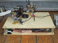
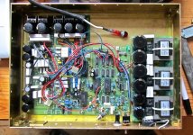
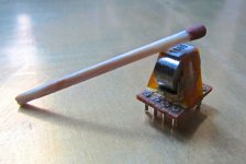
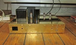
- PCM63 resistor Value