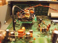
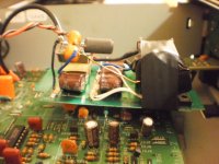
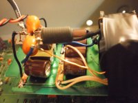
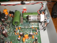
I've searched and it seems that everyone who has reclocked the cd63 is either using a Kwak or Audiocom or LCAudio or some standard reclocking modules.
Recently I tried a direct reclocking method using a 16.9344MHz (I'm not sure if its a TCXO or a VCXO as its a crystal salvaged from a Primare CD20 cdp) and feeding its 16.9344MHz output directly to the pin 28 of the chip SM5872BS to no avail. It does not work. Adding some resistance and capacitor to remove DC offset also does not work. Am I missing something?
Please share your experience using a direct TCXO/VCXO reclocking.
PS: All due diligence has been done i.e. removed CD02, CD03, RD02 and XD01 (refer to CD63 service manual)
cheers
Last edited:
Put an electrolytic capacitor in between the 2mH and the XO and ground (100-300uF). This ground must be connected to the ground plane in your player. If this does not help, you have to check that you are connecting the power and gnd to the right pins on the XO. See datasheet: http://www.golledge.com/pdf/products/osc_ld/gxou101.pdf You have to check what pin 1 does on your XO. Have a look at the circuit it is taken from and find out if it is an enable signal of some kind or if it is not connected.
This should be straightforward, and should work if the output is the correct frequency. The value you measure with your DMM depends on the duty cycle of the output of the XO.
This should be straightforward, and should work if the output is the correct frequency. The value you measure with your DMM depends on the duty cycle of the output of the XO.
Last edited:
I didn't elaborate on my 5v, it's connected this way:
7805 -- 2x470uf -- 1mh -- 2x470uf -- 1mh -- 2x470uf -- ferrite -- 100uf -- XO
The XO I'm using is an ESKA MCO-7100A. It's a DIL14 package
ESKA CRYSTALS - Fast Worldwide Delivery of Quartz Crystal Units
Looking at the data on the DIL14, it seems that pin1 is just NC.
I'm still not getting it. Yeah I'd agree this should be a straight forward implementation. I've done it on my Behringer DCX2496 and DEQ2496 using a Tentlabs 24.576Mhz TCXO.
How can you know whether the changes you have made have improved the clock without looking at the waveform with a scope, and even that will only give an arbitry indication of any improvements, or just buggering the signal up. You need some specialised equipment to measure jitter etc. Nor yours ears cannot tell you what is going on in the digital domain, you need to use measurement and see what is happening, to think otherwise is stupid. The clock is one of the most critical signal of many digital designs, and just replacing one thing with another without any investigation or equipment to monitor the changes, is just playing, you have no metrics to compare changes to, other than your ears, which are useless in this case.
Nor yours ears cannot tell you what is going on in the digital domain, you need to use measurement and see what is happening, to think otherwise is stupid. The clock is one of the most critical signal of many digital designs, and just replacing one thing with another without any investigation or equipment to monitor the changes, is just playing, you have no metrics to compare changes to, other than your ears, which are useless in this case.
You're telling me you can't hear the difference between a 2 pin crystal and a simple TCXO ? Then you gotta train your ears more and stop typing this stoopid comment. Bugger off if you can't be of help. I really don't need children screaming.
Will who's system doesn't work. AQs to the rest its not engineering it playing, you have no idea what you are doing without something to look at the clock signal.
I am not a child screaming, actually, I have first hand knowledge about how critical clock signals are for digital design.
Children mess with things they don't understand.
As to telling the difference with your ears, I doubt that...
I am not a child screaming, actually, I have first hand knowledge about how critical clock signals are for digital design.
Children mess with things they don't understand.
As to telling the difference with your ears, I doubt that...
Is pin 1 connected to (part of) the metal casing of the XO ?
After your pointer of the pin1, I read up and then tried all 3 configs - with 5v, gnd, and nc. They all didn't work.
I've also inserted a 0.1uf cap after the tcxo - that also didn't work.
I guess my other question is, can the cd63 actually accept the signal given off by a tcxo?
I've done several Kwak Clock7 into a cd63 and cd67 and they all worked the 1st time.
cheers
faulty tcxo
After swapping the freggin tcxo with another precision 0.5ppm 24.576MHz, its working now.
Pin 1 remains n/c.
Therefore it's confirmed, a tcxo fed by a 5v is suitable for a Marantz cd63.
Lying naked at the moment, soon I'm going to box it.

The bottom layer pcb is actually an entire ground plane.

L-C-L-C-L-C filtration

This player was already modded with its dac connected to an anode follower so it is very responsive to any tweaks.
With the precision clock, what an amazing improvement it made to the overall instrument clarity and separation
cheers
After swapping the freggin tcxo with another precision 0.5ppm 24.576MHz, its working now.
Pin 1 remains n/c.
Therefore it's confirmed, a tcxo fed by a 5v is suitable for a Marantz cd63.
Lying naked at the moment, soon I'm going to box it.

The bottom layer pcb is actually an entire ground plane.

L-C-L-C-L-C filtration

This player was already modded with its dac connected to an anode follower so it is very responsive to any tweaks.
With the precision clock, what an amazing improvement it made to the overall instrument clarity and separation

cheers
Last edited:
I would not be surprised that if you actually looked at the signal from the clock it would be worse than the original device, with the long lead and impedance mismatches.
Now you may say I am rude, but I am being realistic, that is not how to do clock signals. They like short traces, no impedance mismatches, constant proximity to the ground plane. To do it like that you would have to simulate the leads, traces etc and use some form of termination to guarantee a clean problem free waveform, so you minimise jitter added due to non optimal signal routing.
http://www.digikey.co.uk/Web Export/Supplier Content/CTS_8006/PDF/CTS_AN1025.pdf?redirected=1
The 10 Best Ways to Maximize Emission from Your Product
Not exactly. It's quite probably a worse source than the onboard crystal-based Pierce oscillator. You've replaced a crystal with an active part containing a PLL with unknown sensitivities when these things - TCXOs - are not definitely first choice for low jitter (claimed ppm accuracy has nothing to do with that, at all).Therefore it's confirmed, a tcxo fed by a 5v is suitable for a Marantz cd63.
The best one can say is - the cd player still works.
Not exactly. It's quite probably a worse source than the onboard crystal-based Pierce oscillator. You've replaced a crystal with an active part containing a PLL with unknown sensitivities when these things - TCXOs - are not definitely first choice for low jitter (claimed ppm accuracy has nothing to do with that, at all).
The best one can say is - the cd player still works.
Have you even tried it and then have a good listen to the final sound to conclude that the TCXO is a poorer selection?
Pretty much the same argument with non oversampling modifications. Tech junkies will stick to their text book to claim Mr. Kusunoki is an idiot for performing that act.
To me, it's the final sound that matters.
nuff said. stop theorizing.
No. It's based on a bunch of experience.
One good clock, even Pierce IC-based +'quiet' supply, does the job. Nailing-on things one doesn't understand might work - but if you've no way of understanding - let alone measuring how or why - why bother. Audition takes you only so far.
More succinct summary: tcxo and vcxo 'clocks' are well-understood to perform fairly-to-very poorly in terms of phase noise. PPM claims have nothing to do with 'low jitter', nothing at all; got that?
Using a clock that wanders in response to a noisy stimulus (as a vcxo/tcxo is designed to do) adds an unknown clock source *and* an unknown/uncontrolled correction/wander in series, when you could just have given the existing reasonable clock a quieter PSU.
(acoustica.org.uk: modifying the Marantz CD63, part 1) (and yes, that's me a decade ago; right intent, at least)
- Status
- This old topic is closed. If you want to reopen this topic, contact a moderator using the "Report Post" button.
- Home
- Source & Line
- Digital Source
- Marantz CD63 reclock with direct TCXO
