Is simpler to improve the input stage to make it immune to voltage variation in the rail , is better to leave the ccs cascoded by the output stage. Believe-me .
Or... not believe
 . in simulation it seems there is nothing to gain in cascoded the ccs with the output stage, but with measurements in the prototype it was better, i have to take a better look.
The CCS can also be bettered by inserting a Jfet CCS instead of the two 10 K.ohm resistors, then you take the influence from Rail variations out.
I like the scaling by inserting more current-summing legs, as apposed to unbalancing the mirror.
Casodede mirrors are more than 10 fold higher in impedance and with the beta helper you can get really High.
I like the scaling by inserting more current-summing legs, as apposed to unbalancing the mirror.
Casodede mirrors are more than 10 fold higher in impedance and with the beta helper you can get really High.
Also, your cross-connected Baxandall type VAS is good but I compared it to the traditional complimentary Common-base Baxandall VAS and it has inferior PSRR. Have you tried Edmond's arrangement in figure 5 here?
I have now simulate the two circuits. And i also get just a little beter PSRR with the baxandall pair but its a minor difference, and i have better distortion figures with my type of connection also a minor diference. Both get good behavior with a square wave input.
I do not care to much about PSRR because the power supply that i use have already very low noise, it is similar to your The K Multiplier
In the begining i use only capacitance multiplier, with very low noise also but using a cfp gives a lower output impedance, there is very low A.C. current in the power supply rails, so the output impedance of the power supply is not that important.
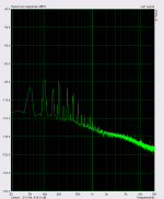
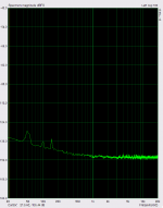
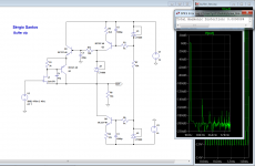
The first picture are the output noise of a 7815 regulator , second the noise at the output of the cfp capacitance multiplier.
The third picture is the measurement of distortion of the real circuit with a input impedance of 3k 8ma p-p and 2v rms out (is the same as the sound card i use) .
Attachments

Last edited:
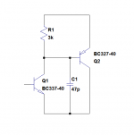
The CCS can also be bettered by inserting a Jfet CCS instead of the two 10 K.ohm resistors, then you take the influence from Rail variations out.
Yes using a jfet ccs will be better, the resistors were used for the dc servo . The variations in Vce of the ccs transistor will make variations in the base current , so for take the influence from Rail variations out, you have to insure that the Vce from this transistor is stable, one way is cascode it with a fet or mosfet.
This is a preamplifier with the same principles that we are talking here, it has a gain of 16x with 250 ohms in R2 if you want lower gain you have to increase this resistor 500 ohms for a gain of 8x and 1k for a gain of 4x. the maximum voltage out is 16 volts p-p.
I have post it here with other 2 for my one and there are also some circuits design by Dado and keantoken, I recomend that you take a look.
http://www.diyaudio.com/forums/analog-line-level/223835-current-conveyor-voltage-amplifier-16.html
The distortion is 0.000069% at 4 V p-p with a gain of 16x
This is a basic circuit and can be improve further , It also needs a output buffer to lower the impedance , but that is another story.
I have post it here with other 2 for my one and there are also some circuits design by Dado and keantoken, I recomend that you take a look.
http://www.diyaudio.com/forums/analog-line-level/223835-current-conveyor-voltage-amplifier-16.html
The distortion is 0.000069% at 4 V p-p with a gain of 16x
This is a basic circuit and can be improve further
, It also needs a output buffer to lower the impedance , but that is another story.Attachments
Last edited:
As I understand you referenced the drivers to the rail to effectively cascode the CCS. However this leaves the input stage open to rail variations. If you decouple R15 with a lytic and delete R10/R24 decoupling, and then improve the CCS, you will lave less overall Iq modulation which I think will result in more PSRR.
You are right Kean , is better to have the voltage reference to ground, Thanks very much for the tip .
Joachim have already advice for that matter some time ago. And at that time i did not see it . I will make that change.
kean using a global feedback loop is a possibility , but I will not go that way , at least not now.
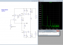
Instead i present a simple buffer that uses a complementar feedback pair , I know much of people in this forum don´t like cfp , but i found it very interesting .
I think that much of the bad reputation that cfp has, is because people do not use a mean to prevent oscilations that can occur in some situations.
In a not so long time ago i expriment a I/V converter with a differential cfp pair and when i was measure distortion , some times a little oscillation of high frequency occurred, but as all of the circuits that i had seen with cfp do not has any mean of oscillation prevention, i did not use any also , inserting a capacitor C1 like in this pictures is very effective in stabilize the cfp loop, that sollution work very well .
Attachments
Last edited:
CFP buffer
And here is the circuit of the buffer with a fet at the input the distortion is very low (0.000008at 4 Volts p-p ) mainly 2º harmonic , at 16 Volts p-p the distortion is 0.000033% with a 10k load.
R13, C2 is essencial for the circuit , do not omit them.
this buffer can be use with all of the circuits post here
Attachments
Last edited:
CFP and bootstrapped cascode - both raise the order of the system, may have unobvious feedback, problems at RF frequencies where device, interconnect unmodeled parasitics, coupling are important
while spice sims can in principle be augmented with models for the parasitics it is not cookbook, sometimes you just have to resort to hardware, stoppers, Zobels, lossy ferrite and a really fast 'scope (with a learning curve on how to probe for 100 MHz parasitic oscillation too)
while spice sims can in principle be augmented with models for the parasitics it is not cookbook, sometimes you just have to resort to hardware, stoppers, Zobels, lossy ferrite and a really fast 'scope (with a learning curve on how to probe for 100 MHz parasitic oscillation too)
Sergio, why not use a signal generator to probe the AC response directly and identify problems in the real prototype that way? You may stop oscillation, but this doesn't mean the device is free of peaking and step response anomalies.
I ordered a bunch of ferrite beads a while back which have been sitting in a bin. These can be quite helpful. I wish I had tried them out sooner. They're easy to test on a prototype and instantly reusable. Like any reactive component, you have to know how to use them, but they can make you work less for the same result
I ordered a bunch of ferrite beads a while back which have been sitting in a bin. These can be quite helpful. I wish I had tried them out sooner. They're easy to test on a prototype and instantly reusable. Like any reactive component, you have to know how to use them, but they can make you work less for the same result
If for some reason you guys dont share my passion by the cfp
here is a boring buffer with a fet, the distortion with 4 V p-p is 0.00057% 10khz, 10k load, but it has a good harmonic profile with maily 2º harmonic and the 3ª at -140db
smms,
With very low source resistance drive, It's not too hard to bottom out
Ltspice's distortion analyzer, ie; zero distortion.
I recommend using various drive impedances from a few hundred ohms to 10k
at 20kHz freq. This will quickly reveal real HF linearity. It will also make the
buffer more suitable for low current DAC's such as 1704 which are going to
invariably have a high(ish) OP impedance / load R. Same goes for load, go
for good linearity driving 1k.
I always do my sims at highest source impedance, 20kHz, lowest (1k/600R)
OP loading. If you can get very good linearity in these conditions you know
it's a decent design.
T
Also, try an inductive source impedance, from several hundred nH's to hundreds of uH's. R13/C2 looks potentially problematic and may make it prone to oscillation with inductive source impedance. This can usually be fixed with an input shorting cap, but point is to be aware of the issue so that you know what is going wrong and why in case of problems.
Thanks kean and zen for the suggestions .
I have try the cascoded cfp with 25k input impedance 30Khz 4volts p-p, and the distortion was 0.00003% with a 10k load.
With 2k load the distortion is 0.0002% . with 1k load the distortion is 0.0013% . I dont recomend use this type of buffers with less than 5k ohms loads , is better to use a push-pull at that low loads.
The parasitic capacitances of the input jfet create distortion when drived by a high input impedance source. But using a bootrapped cascode insures that there is no voltage variations in this non linear capacitances. Without the cascode the distortion with such a high input impedance would be much higher.
At 25k input impedance reveal that C1 is problematic, and is better to not use it.
I have not yet evoluate this buffer design and I have not make a prototype of it yet , but when i have a spare time i will do that, the type of buffer that i use is a bjt cascoded diamond, very low distortion with low load , but is more complex than this.
keep in mind that the schematics that I post are usually ideas, and need to be further evoluated , especially for stability. That is the case of this buffers.
From now one i will include a note of warning in the schematics that i post.
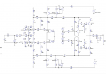
This is an example of the method i use to look for stability problems. In real life pcb traces are not perfect connections, they have inductance. So I put small inductances in the connections between components .
Also do not use perfect capacitors in simulations , use serie inductance and serie resistance in capacitor proprieties.
Adding this inductances make a lot of difference , and the simulation more like in real life.
As I said a simulation is as good as the models we use, that include the traces between the components.
I then simulate with fast rise and fall square waves, and sine.
But of course building a prototype is a must.
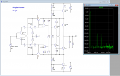
This picture is from the evolution of the tagus-ess ,
This is a very stable design, the loop create by the hawkesford connection is the one that deserves more attention, I have lost many hours with this design and i think it does not have loose ends.
this picture is only an example, not a functional schematic.
Also do not use perfect capacitors in simulations , use serie inductance and serie resistance in capacitor proprieties.
Adding this inductances make a lot of difference , and the simulation more like in real life.
As I said a simulation is as good as the models we use, that include the traces between the components.
I then simulate with fast rise and fall square waves, and sine.
But of course building a prototype is a must.
This picture is from the evolution of the tagus-ess ,
This is a very stable design, the loop create by the hawkesford connection is the one that deserves more attention, I have lost many hours with this design and i think it does not have loose ends.
this picture is only an example, not a functional schematic.
Attachments
Line stage looks really good, open-loop and with the possibility of an truly non degrading volume-control...
Non degrading volume control
Michael, can you tell me why ?
- Status
- This old topic is closed. If you want to reopen this topic, contact a moderator using the "Report Post" button.
- Home
- Source & Line
- Digital Source
- dac I/V convertion with very low distortion