Latest checks:
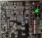
Pin 1 and 11 on WM8805 read 3.28 VDC. Pin 22 still not tied but shows same continuity to those that are.
Middle LED lights with both toslink and RCA s/pdif. The switch properly selects between formats. This makes me think all the main voltages are in the proper range.
Have not purchased the Tenor module yet as I believe the other two formats should function without it. Is that correct? It is not a very expensive purchase but don't want to buy it if the problem is elsewhere.
There is no longer a ghost replica of sound. Now it is dead silent on both optical and s/pdif.
If anyone has suggestions for other points to measure please post. Also looking for good guesses about what most likely could have been fried by the first set of wrong voltages.
I'm not in panic mode and see this as one of those projects one nibbles at from time to time.
Bob,
Looking at your voltage readings in post #66 of this thread, I see that the LT7805 output voltage is 0. Have you fixed that yet?
Stick with it. This is my first USB DAC, and I will not go back to my CD player. This DAC sounds so much better to me than the CD player. I bought it thinking it would be a playground for experiments. Now I don't want to disconnect it. I'd rather just listen.
I might add that, yes, the unit should function without the Tenor module.
I think you might check electrolytic capacitors for opens and shorts caused either by reversed polarity or overvoltage. It is hard to say whether any of the ICs got fried. I think you mentioned you have test equipment to check the board for hot spots. Any changes lately?
I think you might check electrolytic capacitors for opens and shorts caused either by reversed polarity or overvoltage. It is hard to say whether any of the ICs got fried. I think you mentioned you have test equipment to check the board for hot spots. Any changes lately?
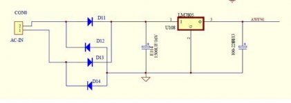
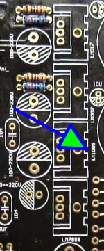
These are the continuity paths for the LT1085 reg as I can decipher them. I swapped the two 100-220 caps thinking one might be defective but got the same readings. This is a replacement 1085 I had on hand and thought it was new but I'm ready to order a new one.
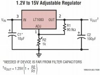
Is there anything in these photos that would affect the output of the regulator? It is still reading 13.3 in - GND - 0.0 out.
Is there anything in these photos that would affect the output of the regulator? It is still reading 13.3 in - GND - 0.0 out.
Attachments
Bob,
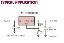
It looks as if the LT1085 is being used as shown in this circuit from the datasheet, where R2 is set to 0 ohms. In that case, the given formula says the output should be 1.25V. You're not far off with 1.46 V. Note that I got the pinout confused. The WM8741 needs 5 V, not 1.46 V, so I wonder if LT1085 is the right part. Although my board uses an LM7805 in that position, the LM7805 has a different pinout, so it is not a direct substitute. I wonder if there are any 5 V, 3-terminal regulators with a pinout such that pin 1 is Gnd, pin 2 is Vout, and pin 3 is Vin. It seems that such an IC would be the right part. I would personally be tempted to fit an LM7805 but bend the pins around to match the board.
It looks as if the LT1085 is being used as shown in this circuit from the datasheet, where R2 is set to 0 ohms. In that case, the given formula says the output should be 1.25V. You're not far off with 1.46 V. Note that I got the pinout confused. The WM8741 needs 5 V, not 1.46 V, so I wonder if LT1085 is the right part. Although my board uses an LM7805 in that position, the LM7805 has a different pinout, so it is not a direct substitute. I wonder if there are any 5 V, 3-terminal regulators with a pinout such that pin 1 is Gnd, pin 2 is Vout, and pin 3 is Vin. It seems that such an IC would be the right part. I would personally be tempted to fit an LM7805 but bend the pins around to match the board.
Attachments
I thought about substituting a LM7805 but it looks like this may be one of those version differences. The print mask clearly has the LT stamp, so it would appear the designer used it intentionally. I'm open to trying the swap if you still think it is necessary.
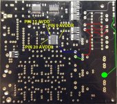
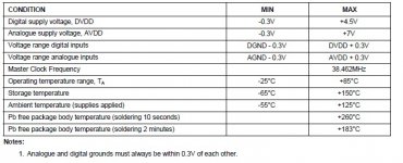
Also all the AVDDX pins show a range for voltage. Are there any other pins on the WM41 where 5V might show up? Don't want to be probing where I shouldn't be.
Also all the AVDDX pins show a range for voltage. Are there any other pins on the WM41 where 5V might show up? Don't want to be probing where I shouldn't be.
Attachments
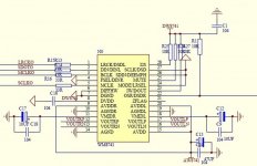
These boards only have one way to change filters, and it changes the oversampling rate, too. There's a DIP switch that sets pin 22 on the WM8741 either high or low. I think you should be able to cut traces and add your own DIP switches to use hardware selection of the filter.
I did not know that Weiliang had a version that allowed software control. Interesting.
I did not know that Weiliang had a version that allowed software control. Interesting.
Do any of these new ebay boards have software control (I2C) of the wm8741 to allow changing filters? Or is the $320 Weilang the only option for that?
Last edited:
Bob,
Those are the absolute maximum ratings you show from the WM8741 datasheet. Look on the next page, and you will see the recommended operating conditions and test conditions, which both show 5V as the normal analog supply voltage. I don't think there are any other pins on the IC that should read 5V--just the ones you traced out on your own board.
It is possible that your board is somehow defective being that pin 1 of the LT1085 is grounded on your board. Is there any evidence of that? Are there any resistors connected to pin 1, that should be there for normal operation?
If you're hesitant to experiment, why not drop a note to either minishow0328 or along1986090 and ask.
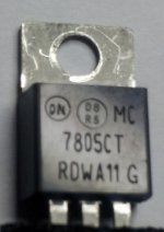
FYI, LT1085 voltage regulator are confusing ! there exist in both fixed and adjustable version. A substitute for LM7805 is LT1085_fixed_5V.
LT1085-Fixed - 3A, 5A, 7.5A Low Dropout Positive Fixed Regulators - Linear Technology
LT1085-Fixed - 3A, 5A, 7.5A Low Dropout Positive Fixed Regulators - Linear Technology
So which one appears correct for this application? Here are my choices.
Integrated Circuits (ICs) | PMIC - Voltage Regulators - Linear (LDO) | DigiKey
Can't see a distinguishing mark on the LT.
Also found a third in my drawer:
http://www.chipswinner.com/DS/MC7805.pdf
Integrated Circuits (ICs) | PMIC - Voltage Regulators - Linear (LDO) | DigiKey
Can't see a distinguishing mark on the LT.
Also found a third in my drawer:
http://www.chipswinner.com/DS/MC7805.pdf
Attachments
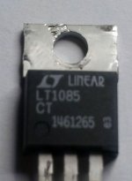
those with label ending with CT are adjustable version.
The fixed voltage label ends with LT1085CT-5 for 5V. You need it in TO220 package.
LT1085CT-5 Linear Technology | LT1085CT-5-ND | DigiKey
LT1085/1086 have better specs than the common 7805. Not sure the difference will be audible though
BTW, given the low current needed, LT1086CT-5 should be sufficient in this application. LT1085 is the high current version, up to 3A. I wonder why Weiliang picked this one ! As the price is similar, it does not make a difference anyway.
there is a rule in electronics. Whatever the size of your stock, there is always a missing partAnything else you think I should order as backup/just in case - since I'm paying the freight charge already?
These boards only have one way to change filters, and it changes the oversampling rate, too. There's a DIP switch that sets pin 22 on the WM8741 either high or low. I think you should be able to cut traces and add your own DIP switches to use hardware selection of the filter.
I did not know that Weiliang had a version that allowed software control. Interesting.
It is possible that the Weilang is using relays to select filters in harware mode (audio-gd does this silly work around), but it looks like they are claiming the ability to select all 5 filters at each sample rate which is only possible with software control. Hoping to see a "budget" ebay board like these with software control of the WM8741 show up.
Here is a new derivative from a highly respected vendor. Don't know if it will be offered as a kit or if it has a software hook.
Dual WM8741 DIR9001 input plus PCM2706 USB AD797 analog output ultimate DAC ! | eBay
Dual WM8741 DIR9001 input plus PCM2706 USB AD797 analog output ultimate DAC ! | eBay
Got good results with the new reg but still not there yet. Audio is being produced on both channels - Hooraaayy !!
However the quality is very poor. There is a static mask plus distortion the makes the signal unusable.
It can be heard here.
Does that sound familiar to anyone.
S/PDIF is still not working (though its signal is shown as present by the LED) but optical is alive. There is enough progress that I'm considering getting the Tenor module now.
Thanks so much for all the help and direction to get to this point.
- Home
- Source & Line
- Digital Source
- WEILIANG DAC5 - WM8741 & Tenor TE7022