If you guys are going to build the cathode broskie follower only, there won't be voltage amplification so there's a chance the signal will be very low. The first stage in the unbalancer is to voltage amplify the DAC output.
I built both but I upgraded to the unbalancer because of lack of amplification. Both sound great.
I built both but I upgraded to the unbalancer because of lack of amplification. Both sound great.
Having started working with a kit, not an assembled unit, after the experiment was working .There was a lot of spare parts
Just remove the 4 resisters that pass the I2S bus to the DAC and link the I2S bus from the USB convertor
I used the resisters that were to fit in that location.(I don't really think the the resister are needed, links would do)
Keep the lenghts of the links short
I2S is the link I hoped to use on interface with this DAC. Problem seems to be that I2S links need to be short, which is physically impossible if you don't put the DAC inside the DAC or DVD or CD player. That certainly sort of limits using it with different players.
If you have any suggestion on how to solve that, adding I2S output interfaces on players that would allow longer cables, like a buffer or something, that should be great.
Looking for Confirmation
Am I correct in assuming (I did browse the thread) that there is no need to add any jumpers or cut any traces when applying Dario's upgrade BOM? I'd rather ask a silly question than see green smoke.
Also would appreciate a little more info on the Brown Dog mod. Soldering is completed but I only found one reference to the bypass cap.
Thanks
yes, you don't need to cut or jump any traces, when applying Dario's BOM
Also would appreciate a little more info on the Brown Dog mod. Soldering is completed but I only found one reference to the bypass cap.
Hi Bob, the upgrade BOM requires only components swapping, no trace cuts or bridges.
The OPA827 10nF bypass should be mounted on pin 4 and 8 of the browndog.
I've recently discovered that OPA827 changes a lot as time passes in the bass firmness (the bypass is there for that reason), BTW the bypass don't hurt.
Maybe you could start with the bypass and remove it after 50 hours so you can say us if it's really needed...
Attachments
Last edited:
I2S
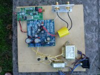
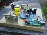
The Pictures show how the wiring has been done
This then feeds a DIY Aleph Preamp followed by PSE 6CA7(Triode Connected) monoblocks and Goodmans 201 Open Baffle Speakers
Using the DAC in this way and using a PC as a source has provided a source that leaves my Esoteric transport and Wadia DAC in storage.
A PC using USB DAC is a VERY effective source.
I don't know why CD material sounds better from the hard drive but it does.
Using programs like Foobar, upsampling can easily done.
This is the reason that the I2S can be kept short and still provide a great source to the rest of the system
Mark
Which specific converter USB/I2S (eBay?) are you using? Any photos available?
How is it wired at the output? Just cap or cap + resistor? Where does it go to from there: preamp, volume pot, power amp?
Very interesting approach, Mark. Both on input and output. And regulators, of course.
The Pictures show how the wiring has been done
This then feeds a DIY Aleph Preamp followed by PSE 6CA7(Triode Connected) monoblocks and Goodmans 201 Open Baffle Speakers
Using the DAC in this way and using a PC as a source has provided a source that leaves my Esoteric transport and Wadia DAC in storage.
A PC using USB DAC is a VERY effective source.
I don't know why CD material sounds better from the hard drive but it does.
Using programs like Foobar, upsampling can easily done.
This is the reason that the I2S can be kept short and still provide a great source to the rest of the system
Mark
Attachments
The Pictures show how the wiring has been done
This then feeds a DIY Aleph Preamp followed by PSE 6CA7(Triode Connected) monoblocks and Goodmans 201 Open Baffle Speakers
Using the DAC in this way and using a PC as a source has provided a source that leaves my Esoteric transport and Wadia DAC in storage.
A PC using USB DAC is a VERY effective source.
I don't know why CD material sounds better from the hard drive but it does.
Using programs like Foobar, upsampling can easily done.
This is the reason that the I2S can be kept short and still provide a great source to the rest of the system
Very nice arrangement. Very well executed. Congratulations.
Some questions:
1) What regulator is that your using for 5v? Burson?
2) Shouldn't you load the output with a resistor too? If it's there I can't see it.
I'm considering the Teleporter option for I2S interface too.
Nicely done! I guess I'll try the same converter. It's compact and I can put it in my DAC casing use a direct USB connection. Great!
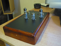
By the way, this is my DAC project. Don't laugh at me, I'm still a learner and It's my first tube project and I suck at applying shellac, but I'll repair it later. I want it to completely dry for now. The good thing is, I made the enclosure with separate sections, the top plate with the tubes is removable, so I can work on the wood chassis at anytime.

http://store.picbg.net/pubpic/26/2E/cf869397de9a262e.png
http://store.picbg.net/pubpic/DE/B7/c5dc7160b331deb7.png
Inside will be the unbalancer with tube voltage regulators (no sockets for the reg tubes for now). There will be silver wire for direct signals from the DAC and tubes and from the converter I2S to DAC. Connectors will be separate - one for heaters, one for B+, one for DAC V+ and one for USB. There is a Salas shunt reg for the analog part of the DAC, I have space for some compact regs for the low current digital ones (may try with finesse)?
The resistors are 1% Tesla TR military grade metal film, signal caps are K40u9 russian PIO with their metal casing removed and ETO-3 russian military AgTa to the output. There are some carbon resistors too where I didn't have right values.
The switch will be turned from the front using an aluminium axis
By the way, this is my DAC project. Don't laugh at me, I'm still a learner and It's my first tube project and I suck at applying shellac, but I'll repair it later. I want it to completely dry for now. The good thing is, I made the enclosure with separate sections, the top plate with the tubes is removable, so I can work on the wood chassis at anytime.


http://store.picbg.net/pubpic/26/2E/cf869397de9a262e.png
http://store.picbg.net/pubpic/DE/B7/c5dc7160b331deb7.png
Inside will be the unbalancer with tube voltage regulators (no sockets for the reg tubes for now). There will be silver wire for direct signals from the DAC and tubes and from the converter I2S to DAC. Connectors will be separate - one for heaters, one for B+, one for DAC V+ and one for USB. There is a Salas shunt reg for the analog part of the DAC, I have space for some compact regs for the low current digital ones (may try with finesse)?
The resistors are 1% Tesla TR military grade metal film, signal caps are K40u9 russian PIO with their metal casing removed and ETO-3 russian military AgTa to the output. There are some carbon resistors too where I didn't have right values.
The switch will be turned from the front using an aluminium axis
Last edited:
Nicely done! I guess I'll try the same converter. It's compact and I can put it in my DAC casing use a direct USB connection. Great!
By the way, this is my DAC project. Don't laugh at me, I'm still a learner and It's my first tube project and I suck at applying shellac, but I'll repair it later. I want it to completely dry for now. The good thing is, I made the enclosure with separate sections, the top plate with the tubes is removable, so I can work on the wood chassis at anytime.
Inside will be the unbalancer with tube voltage regulators (no sockets for the reg tubes for now). There will be silver wire for direct signals from the DAC and tubes and from the converter I2S to DAC. Connectors will be separate - one for heaters, one for B+, one for DAC V+ and one for USB. There is a Salas shunt reg for the analog part of the DAC, I have space for some compact regs for the low current digital ones (may try with finesse)?
The resistors are 1% Tesla TR military grade metal film, signal caps are K40u9 russian PIO with their metal casing removed and ETO-3 russian military AgTa to the output. There are some carbon resistors too where I didn't have right values.
The switch will be turned from the front using an aluminium axis
dude, your work looks stellar!
did you make that unbalancer point to point? is it up and running now? i don't see any B+ and heater regulator in there.. and i can't see the ak4396 chip as well!
Last edited:
No, not yet. I mentioned previously that I had a accident with a typo regulator that burned my DAC chip and I'm waiting for a new one to be delivered.
In the meantime I'm working on this thing.
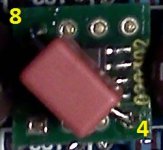
You can see that the DAC IC is unsoldered from the board.
What do you mean by "point to point"? I didn't copy the schematic exactly. I a cap at the positive interstage too, because otherwise the B+ of the second stage is dependant of the 1st one and I have more freedom with tube modes when having DC isolation.
I use 6N1P input and 6N6P output tubes.
Thanks for your comment.
In the meantime I'm working on this thing.
You can see that the DAC IC is unsoldered from the board.
What do you mean by "point to point"? I didn't copy the schematic exactly. I a cap at the positive interstage too, because otherwise the B+ of the second stage is dependant of the 1st one and I have more freedom with tube modes when having DC isolation.
I use 6N1P input and 6N6P output tubes.
Thanks for your comment.
No, not yet. I mentioned previously that I had a accident with a typo regulator that burned my DAC chip and I'm waiting for a new one to be delivered.
In the meantime I'm working on this thing.
You can see that the DAC IC is unsoldered from the board.
What do you mean by "point to point"? I didn't copy the schematic exactly. I a cap at the positive interstage too, because otherwise the B+ of the second stage is dependant of the 1st one and I have more freedom with tube modes when having DC isolation.
I use 6N1P input and 6N6P output tubes.
Thanks for your comment.
ahh.. clever.. so you still can have the unbalancer circuit, but with more wide of tubes variabilities
have you tested your unbalancer? is it working? i think i'm going to go your way. waiting for the pcb is just killing me
but i'm planning to use this thing VERO BLANK PROTOTYPING PCB FOR TUBE CIRCUITS! | eBay instead of real point to point. seems neater
Of course I had made it on a testing board using 6N6P on the input.
Before I made the Lampizator output using a single 6N6P for both channels.
To tell you the truth, the simple lampizator stinks donkey *** compared to the unbalancer, I realized what piece of **** I had built. The unbalancer sounded so much spacy, clean and some parts that were shouting (distorting) were very good now.
I highly recommend it, it's not the top best option I think, but it's not expensive to build IMHO. It also makes a DAC/preamp combo with a buffer.

http://store.picbg.net/pubpic/83/DE/710a791a993283de.jpg
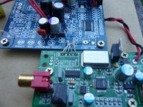
I2S
The Regulator is a Belleson Super regulator
There is no resister but there probably should be
The DAC has been running for about 3 months without it.
I have some spare Kiwame 1200 ohm resisters so these might get a try.
Mark
Very nice arrangement. Very well executed. Congratulations.
Some questions:
1) What regulator is that your using for 5v? Burson?
2) Shouldn't you load the output with a resistor too? If it's there I can't see it.
I'm considering the Teleporter option for I2S interface too.
The Regulator is a Belleson Super regulator
There is no resister but there probably should be
The DAC has been running for about 3 months without it.
I have some spare Kiwame 1200 ohm resisters so these might get a try.
Mark
Hey, I found a unbalancer on ebay (Jim's Audio). It looks like the Broskie.
It will take unbalanced inputs (from a dac) and give you a singled ended output.
Bal/unbal input tube preamplifier stereo PCB ! | eBay
It will take unbalanced inputs (from a dac) and give you a singled ended output.
Bal/unbal input tube preamplifier stereo PCB ! | eBay
It seem to have filtering power supply electrolytics slots, but I think it's a Broskie cathode follower only, there is no voltage amplifier stage.
Why do you need a PCB? The schematic is simple and you have more freedom. You really don't need the electrolytics, my power supply is separate and is a electrolytic free C LC LC LC RC filter.
Why do you need a PCB? The schematic is simple and you have more freedom. You really don't need the electrolytics, my power supply is separate and is a electrolytic free C LC LC LC RC filter.
- Home
- Source & Line
- Digital Line Level
- DAC 2496 (AK4393) DAC KIT With CS8416+AK4393+5532