A friend of mine bought a Sony SCD-XE670, and I followed. It seems like it beats my Pioneer DV333, which beats (in some ways?) my Philips 850. My friend then decided to do mods, and then I followed, only in my own ways.
Here is my version of CD clock: (see attached schematics)
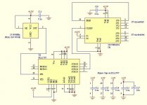
The Burr Brown PLL1707 is a hardware confiurable PLL clock generator capable to output clock signals with jitter down to 50 ps. Comparing to other clock circuits having 2 ps jitter, this may not perform very well. But the 2ps cost USD100 and this one is only a fraction of it. The PLL1707 can use a 27MHz crystal as it has its one chip oscillator, but I chose to use a off te shelf crystal oscillator. It cost more but I have guaranteed signal input. The choice will yours. The PLL1707 is set up to output 11.2896MHz, and works at 3.3V supply, which complies with the original circuit.
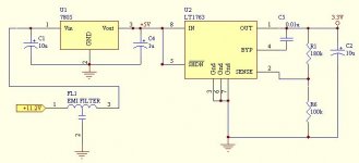
I used double voltage regulator plus a emi filter in the front to have maximum isolation of digital noise between the clock and the rest of the circuits, espically the analog part. The LT1763 has a very low noise output. In fact this may be the lowest noise voltage regulator I know of, 20uVrms from 10Hz to 100kHz.
To make things unnecessarily more complicated, I added a clock driver after the PLL1707, to replace the 74HC04 used in the original circuit. This clock driver chip has higher driver capability, and all the output are perfectly synchronized.
The manufacturers for the IC's are:
7805 - any
LT1763 - Linear Technology
CDCVF25081 - TI
PLL1707- Burr Brown
One thing I would like to remind whoever wants to use the PLL1707 is that this chip is a 25 mil pitch smt part, which is very difficult to do prototype without a properly designed pcb. Make sure you have the workmanship!
Comments are welcome, good or bad.
Here is my version of CD clock: (see attached schematics)
The Burr Brown PLL1707 is a hardware confiurable PLL clock generator capable to output clock signals with jitter down to 50 ps. Comparing to other clock circuits having 2 ps jitter, this may not perform very well. But the 2ps cost USD100 and this one is only a fraction of it. The PLL1707 can use a 27MHz crystal as it has its one chip oscillator, but I chose to use a off te shelf crystal oscillator. It cost more but I have guaranteed signal input. The choice will yours. The PLL1707 is set up to output 11.2896MHz, and works at 3.3V supply, which complies with the original circuit.
I used double voltage regulator plus a emi filter in the front to have maximum isolation of digital noise between the clock and the rest of the circuits, espically the analog part. The LT1763 has a very low noise output. In fact this may be the lowest noise voltage regulator I know of, 20uVrms from 10Hz to 100kHz.
To make things unnecessarily more complicated, I added a clock driver after the PLL1707, to replace the 74HC04 used in the original circuit. This clock driver chip has higher driver capability, and all the output are perfectly synchronized.
The manufacturers for the IC's are:
7805 - any
LT1763 - Linear Technology
CDCVF25081 - TI
PLL1707- Burr Brown
One thing I would like to remind whoever wants to use the PLL1707 is that this chip is a 25 mil pitch smt part, which is very difficult to do prototype without a properly designed pcb. Make sure you have the workmanship!
Comments are welcome, good or bad.
Attachments
I also have the SCD-XE670 SACD Player, I would love to make some Mods and have looked at the SACDMOD website. I think that $350 US is a little steep for me. I would do the mods myself as I am a qualified technician and DIY'er, but I do not have a clue where to start. This clock Mod looks cool, but again I am unsure of implementation.
Anthony
Anthony
Hi Coulomb,
I am glad you are interested in my version of clock.
The sequence I did my mod is as follows,
1. Replaced some of the small caps in the audio section with COG type caps (I don't know what were the original, but I trusted COG's), namely C402,502, C403,503, C412,512; and the 0.015u bypass with polypropylene.
2. Replaced the NJM2114 opamp with LM6172 (this is a 3000V/uS beast).
3. Replaced the 47uF caps. I settled with Kemet AO-cap which has very low ESR. Most mods recommend Rubycon but I just want something different.
4. Upgrade the clock circuit with my "kwok clock", because it is cheap. You may be able to buy the PLL1707 from Digikey (They still have some. This chip is not in their regular catalog), and so as the clock driver.
The total cost should be well below CAD$100, and it is fun!
The result?
I find that replacing the opamp with LM6172 improves the overall sound with more open feel. The low jitter clock gives me much more details at low level and very low level. It is somewhat like the D/A converter suddenly has a few more bits, if you can imagine what I mean. And such improvement is not possible with any other mods, no matter it is replacing with caps, resistors, power supplies or any other way, which is really beyond what I could expected.
I wish to remind you again that working with any of the IC chips requires very dedicate soldering skill, especially with the PLL1707.
I would like to hear from you the result you get.
kwokm
Hi Coulomb,
The connection is at the bottom of the pcb.
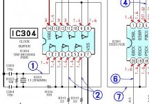
Remove C303,304, R323 and the original xtal X301. Connect the clock output to pin 1 of IC304 (74HC04). This is assumed that you have not built the clock driver. I attached my clock driver chip by unsoldering and lifting up the pins of IC304 and glue the TI driver directly onto the top of IC304, and then soldered the wires directly onto its pins. The outputs of the clock driver will be hooked up to the corresponding outputs from the original 74HC04 chip. Each of the these output has a resistor connected in series before reaching the other input side. You will have to connect the outputs directly to the other input side, since the TI clock driver already has a built in resistor for each outputs.
You can get power from CN306 pins 1 & 2 which is 11.2V unregulated.
Please see the attached diagram.
The connection is at the bottom of the pcb.
Remove C303,304, R323 and the original xtal X301. Connect the clock output to pin 1 of IC304 (74HC04). This is assumed that you have not built the clock driver. I attached my clock driver chip by unsoldering and lifting up the pins of IC304 and glue the TI driver directly onto the top of IC304, and then soldered the wires directly onto its pins. The outputs of the clock driver will be hooked up to the corresponding outputs from the original 74HC04 chip. Each of the these output has a resistor connected in series before reaching the other input side. You will have to connect the outputs directly to the other input side, since the TI clock driver already has a built in resistor for each outputs.
You can get power from CN306 pins 1 & 2 which is 11.2V unregulated.
Please see the attached diagram.
Attachments
")
kwokm said:I thought I have attached it.
Now I can see the Image, though it appears to be cut off on the right side.
Anthony
pll1707 problem
Hello everybody!
I'm new in this forum, so forgive me for all my falses!!
I buy PLL1707 ,so i can produse a 27MHz clock from a crystal(27MHz)!
I think i do all the necessary connections but i take a 9MHz clock as output,in PINS MCKO2 or MCKO1.
Could you explain me why this happens,or what have i connect false?
My connections are:
FS1=1
FS2= 1
CSEL=0
SR=0
Thank you beforehands!
kwokm said:In fact this may be the lowest noise voltage regulator I know of, 20uVrms from 10Hz to 100kHz.
Comments are welcome, good or bad.
Hi,
The regulator is about 60nV/SqrrtHz, not bad, depending on power supply rejection it may be enough.
Honestly, the clock is way too complex. First you generate 27 MHz, then a synthesizer makes 11.2896. Keep it simple !
You may re-use the 11,2896 MHz crystal and build a standard Colpitts oscillator, with a simple style HC04 inverter as a slicer and end up way better than the clock you propose here.
best
I just opened 2 long 4 pin rectangular cristals, one is 33.8 Mhz (from a soundcard) and other is now zero Mhz, (i broke the small cristal itself!)
In it is a small cristall, suspended on 2 springs driving a smd 74HCU04 on a ceramic pcb. The other has a TI031X 301145 chip, couldn't find what chip it is.
Maybe its most simple to buy (or find from scrap) such a VCXO cristal and fit it in CDP with a decent PS. Most simple solution, but sound improvement?
Have a awfull 2000 ps jitter producing cheap DVD/VCR player, it needs a 27Mhz cristal (to Ziva 4.1 chip, the dvd mechanism uses a 33.8 Mhz cristal) Maybe i could try this. The Ziva would benefit most i think.
- Status
- This old topic is closed. If you want to reopen this topic, contact a moderator using the "Report Post" button.
- Home
- Source & Line
- Digital Source
- My CD Clock - the "Kwok Clock"