OMG I'm an ideot.
I connected the diode (back lighting for display) wires to the DOUT (& GRND) & visa versa.
Connected it properly, and now have 1.175v output while playing stereophile disc test tone (-20dB).
just a plain wire connecting DOUT and GRND to the underside of the Gigaworks DAC board where theres a phono plug for input.
No music comes out.
Do I need a phono plug at the end of my DOUT and GRND wires (and/or impedance matching resistors?)
Thanks,
Paul
Hi all,
I've been listening and tweaking my "Shigaclone" for some weeks now.
Expectations were high before first try but i was a little disappointed at first listen because i have a very good reference, Shanling 100MKII with all new Rudolf modified IV ( moded by ZM, implemented by yours trully ).
I've replaced transformer, split supplies and made a shunt one for the 5V and all these mods have steadily improved the sound, especially the new 5V supply.
So yesterday i decided to try detaching the electronics from the transport itself, this was easily done and after putting the thing together again i listened for change.
Sound was gorgeous....but drive was skipping ( loosing lock ), this confused me because it played flawlessly before and i made no changes except a longer flat cable.
There is a major improvement in sound...when i can hear it...but the skipping i have no idea what is provoking it.
Any suggestions from the more experienced on this issue will be very appreciated as now i can finally hear, albeit bits at a time, the magic.

Hi CeeVee
I would try to place electronic board under the mechanism to be able to use original ribbon cable.This way you can make exact situation after previous supply mod when everything was correct.I feel that this ribbon might be too long for such sensitive signals and the reasons for skipping can be some kind of disturbances (in longer signal transfer or emi and rfi).In one post in the beginning of the forum the author wrote that this transport have big advantage sound wise because it uses very short ribbon.Relocating the board can take ten minutes of work and as I can see you have plenty of place and wire so why don't try this. If original ribbon will be to short just put some spacers under the board and test it this way.
Before doing all this I would finger spin that big cog wheel on the right side of the mechanism to check if actuator have some mechanical obstructions.It have to move constantly smooth from beginning till the end.If not check the wheels for dirt or anything else on them and of course that shiny actuator rod for grease.Maybe you got some peace of solder on wheels when you desoldered the board and soldered the new switch board to the motors.Such things happens when we mod.
uncle_leon , Eric
I am glad that you like that.Unfortunately ,there is no forum or link to do that.The only thing that helped me was to see the ingenious Jinji Kimura's job on his transports so I reversed the PiTracer concept to give a cd lens less work to do.The lens is most sensitive part of mechanism and this way the air bearing version is sounding completely different from all transports that I listened. Most players have the same lens vibration problem and this air bearig way we only need to fight the speakers feedback like in analog turntable but in less degree respect to analog.In classic cd transport we don't have to big demand to fight external feedback but the actuator and spinning motor are doing what the speakers are doing in analog turntable so why don't eliminate Cd spinning vibrations.That is all.
If I am not mistaken our transport have very small degree of electronic bit correction and without any mod it sound different (better).So the point is to minimize reading errors to get even better reproduction and I can hear that at the moment.For example the damaged disc skipping is not annoying any more like in every other player and the music have magic but in neutral way unlike many colored turntables do when you are not able to hear the timbre differences.If you want to go this or some different way I am here.
Last edited:
Thanks NoSmoking, nemo,
In fact the flat cable might be the culprit because if i touch it while playing ( but no sound...no lock ) it brings sound back in momentarily and looses it again....
Playing with the lazer power pot ...this shortens lazer life doesn't it ?
Or is the pot for focus ?
In fact the flat cable might be the culprit because if i touch it while playing ( but no sound...no lock ) it brings sound back in momentarily and looses it again....
Playing with the lazer power pot ...this shortens lazer life doesn't it ?
Or is the pot for focus ?
Last edited:
Thanks NoSmoking, nemo,
In fact the flat cable might be the culprit because if i touch it while playing ( but no sound...no lock ) it brings sound back in momentarily and looses it again....
Playing with the lazer power pot ...this shortens lazer life doesn't it ?
Or is the pot for focus ?
I wouldn't touch the pot until you change the ribbon.After all , before longer ribbon mod everything was OK so the lens should be in working condition.Try that original short ribbon.You don't have to screw electronic board on the base of the player, just keep it in your hand for diagnostics.This is the simplest way to find out what is the problem.
For protection against eventual static electricity discharge just resolder the protective blob on lower left angle on the lens near the ribbon connector while disconnecting old and connecting new ribbon and then desolder it again.I never fried the lens that comes without the protective blob but since there is protection it is better to use it.
Is there anywhere out there to find one of the donor boomboxes anymore? I've tried every search I can think of and have come up empty.
Would it be possible to try something like this with a newer dvd/cd player. I've seen some models that now have 24/192 dacs on board. Would it be worth trying? It may not be the same thing but it could still make a good player possibly.
Would it be possible to try something like this with a newer dvd/cd player. I've seen some models that now have 24/192 dacs on board. Would it be worth trying? It may not be the same thing but it could still make a good player possibly.
Is there anywhere out there to find one of the donor boomboxes anymore? I've tried every search I can think of and have come up empty.
Check for availability of these 2 in Canada:
Amazon.ca: Used and New: JVC RC-EZ31 Portable Boombox with CD Player, Cassette Deck, and AM/FM Tuner
Thanks for the help guys.....
Problem solved.
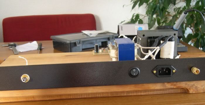
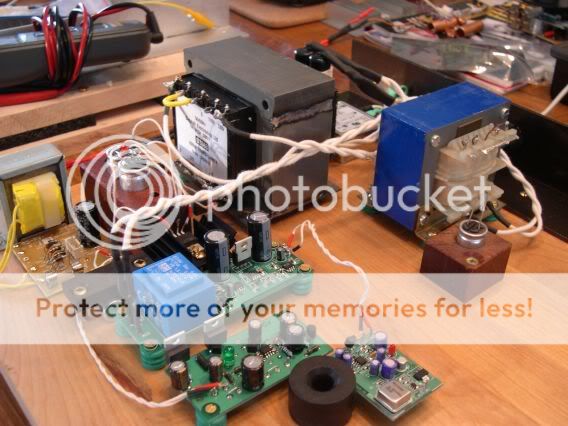
After putting the thing together again, building a solid chassis for it and putting the original short flat cable in, i still had the skipping problem.
So i made a platter adjustment tool ( same as Peter's ).
Raising the platter about 0,5mm did the job.
The help of the lock indicator was also very useful ( blue led from Buffalo DAC in background ).
So now i can continue tests with longer cable and electronics board away from motors......
Problem solved.
After putting the thing together again, building a solid chassis for it and putting the original short flat cable in, i still had the skipping problem.
So i made a platter adjustment tool ( same as Peter's ).
Raising the platter about 0,5mm did the job.
The help of the lock indicator was also very useful ( blue led from Buffalo DAC in background ).
So now i can continue tests with longer cable and electronics board away from motors......
Attachments
Last edited:
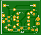
..for those willing to make their own PCBs here is my take for Peter's posted Bobken regulator for the 5V supply.
Please check-it for any mistakes.
I use Bss129 which i managed to source, since Bsp129 was impossible for me.
PCB is 24 X 27 mm and does no include rectifiers and CRC filter, these should be on PSU PCB.
The placing of the output cap is deliberate...it can be placed on it's side if it is too tall to fit in unit.
Attachments
Last edited:
bybee
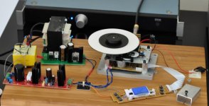
Since I experienced 3 times the positive influence of implementing Bybee's in the AC for the Shigaclone...it was about time to use it myself in the PiTbull.
I had to find out that the larger ones they DOUBLED in price (all over the world) the last month ....due to the used materials...Yeah sure.!!!!..
Anyway as mailed a few times I heard what they did and as a true audiophile I cannot live without it anymore.....so I paid the costs and bought them, I guess you can say " I'd like to get......" .
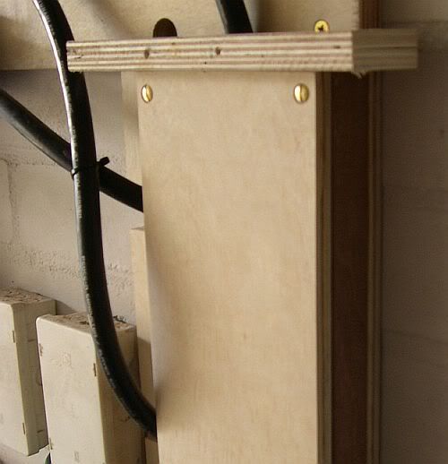
I have no room left for them inside the PiTbull so I implemented them in the Tunami cable...again a happy marriage that cable with the PiTbull.
Here you can see how I did it..mind you soldering is tricky since the sheath of copper innards of the Tunami cannot stand much heat...
I show you before and after...as if nothing happened..
This foto is taken on the other side of the wall (into the workshop) where all the Tunami's come out straight for the fusebox...

Since I experienced 3 times the positive influence of implementing Bybee's in the AC for the Shigaclone...it was about time to use it myself in the PiTbull.
I had to find out that the larger ones they DOUBLED in price (all over the world) the last month ....due to the used materials...Yeah sure.!!!!..
Anyway as mailed a few times I heard what they did and as a true audiophile I cannot live without it anymore.....so I paid the costs and bought them, I guess you can say " I'd like to get......" .
I have no room left for them inside the PiTbull so I implemented them in the Tunami cable...again a happy marriage that cable with the PiTbull.
Here you can see how I did it..mind you soldering is tricky since the sheath of copper innards of the Tunami cannot stand much heat...
I show you before and after...as if nothing happened..
This foto is taken on the other side of the wall (into the workshop) where all the Tunami's come out straight for the fusebox...
Last edited:
Erik -looking good!
Pforeman - you do mean 2 separate wires from the gnd and dout on the shiga to the dac? If you have thats ok. Do you have the resistors on the output to drop the high level ttl signal to consumer level? Your dac might not like the higher signal.
Yes, just one cat 5 wire from DOUT to the input of the DAC (soldered to the underside of the board ((no RCA jack)) ), and one wire from GRND to the ground of the DAC (underside of the board where the ground of the rca jack is).
The system sounds slightly harsh compared to my turntable.
Possibly because those two wires which eventually will only be three inches are right now 18 inches, not twisted, and run past and through ac wires, etc.
But could my system sound harsh (slightly bright) because I'm not using resistors.
Thanks,
Paul
Hi all again,
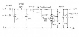
Here are final Sprint PCB files for the BOBKEN 5V Reg board.
First of all with my thanks to Peter.
All small resistors are dale CMF50, 3R 3W MOX resistor is panasonic and the PS cap between between pins 4 and 7 of AD811 is soldered directly to these pins on the copper side, inside IC base if you want to use it or directly to IC pins.
BSS129 orientation is correct, drain pin is tweaked to the shown position to optimize PCB.
Hope it proves useful to the forum.
Attachments
pforeman: I'm not sure if thats why the system might sound bright, but it's a good place to start. The shiga puts out a high level SPDIF signal, and your DAC is expecting a much lower one. It may well be that your DAC doesn't like the high level.....
The other thing is that SPDIF needs to see a constant impedance of 75R to work optimally. With the wiring you suggest, that ain't the case right now. It will work, but not at its best. Put a BNC connector as near as you can to the 300/100 resistors, and then use a 75R coax cable to the DAC.
Fran
The other thing is that SPDIF needs to see a constant impedance of 75R to work optimally. With the wiring you suggest, that ain't the case right now. It will work, but not at its best. Put a BNC connector as near as you can to the 300/100 resistors, and then use a 75R coax cable to the DAC.
Fran
my dac has phono input. Would it be better to use an adapter?
In the beginning (?) of this thread Peter D. made an all in one and said he skipped the resistor network (?).
I thought I'd like the signal going through as few resistors, solder joints etc as possible. Oh well, I think it might be over driving the dac as it seems it is the transient peak that is excessive.
I was thinking of possibly cutting one end off of a digital interconnect and soldering that end to the resistor network?
See pic please. I'm still a little fuzzy about ground connection from shigacl. to dac.
Thanks,
Paul
P.S. Is there a specific resistor type to use (wirewound/metal film?? etc.
I take it at least one watt)
Attachments
You're connecting the shiga to the DAC correctly - it is just gnd and data, but the correct way is to use 75R cable and connectors all the way. All the experts say that RCA jack is not proper 75R, but it does work. So if you have an RCA jack, thats fine.
All you need then is 300R and 91R (some use 100R) resistors - and your pic is correct (300R from d-out, 91R back to GND). Cutting the cable will be fine too, no problem at all.
Resistor types are probably akin to religion - everyone will have their favourites. Standard dale ones will work AOK, try what you have to hand and go for fancier ones later if you want.
Try that first and get the sound clean with no interference, then you can move on to more stuff....
Fran
- Home
- Source & Line
- Digital Source
- Finally, an affordable CD Transport: the Shigaclone story