Hi John,johnm said:
My transformer arrived this morning. Just to make sure I have this right... it's got two secondaries, both 0v - 12v. Do I connect the two 'inner' windings together, and this is my CT which goes to the negative rail. And the two 'outer' tags (0 and 12v) both goto the AC in section?
Cheers,
- John
I think you're right. Just to be clear, in the diagram here :
http://www.airlinktransformers.com/technical-fitting.asp?data=4
the black and yellow wires are tied together to form the CT.
Cheers,
Dennis
I don't have a capacitance meter unfortunately - think I'll get one from Ebay. Sounds like a useful device to have. All the caps have been used before (once) in other projects and they were fine then. I was very careful removing them so I assume they are still OK now.
I've had this with Black Gates before though and then just as I'm about to remove them they quite often come on song!
I'll give it a week and then change the crystal back. If there's no improvement it can only be one of the replaced capacitors.
Thanks for that link Dennis")
I think I need to take a crash course in how transformers work. Still confused. When I tried out my 16v transformer Peter said it might be too much for the LM7808 regulator, unless I used a LARGE heatsink.
However, using this transformer 2 x 12v (a recommended configuration for this project), surely the regulator will have to then deal with 24 volts then? Or have I got this all wrong?
I've had this with Black Gates before though and then just as I'm about to remove them they quite often come on song!
I'll give it a week and then change the crystal back. If there's no improvement it can only be one of the replaced capacitors.
Thanks for that link Dennis
I think I need to take a crash course in how transformers work. Still confused. When I tried out my 16v transformer Peter said it might be too much for the LM7808 regulator, unless I used a LARGE heatsink.
However, using this transformer 2 x 12v (a recommended configuration for this project), surely the regulator will have to then deal with 24 volts then? Or have I got this all wrong?
However, using this transformer 2 x 12v (a recommended configuration for this project), surely the regulator will have to then deal with 24 volts then? Or have I got this all wrong? [/B]
from Wikipedia:
"Full-wave rectification converts both polarities of the input waveform to DC(direct current), and is more efficient. However, in a circuit with a non-center tapped transformer, four diodes are required instead of the one needed for half-wave rectification. This is due to each output polarity requiring two rectifiers each, for example, one for when AC terminal 'X' is positive and one for when AC terminal 'Y' is positive. The other DC output requires exactly the same, resulting in four individual junctions (See semiconductors, diode). Four rectifiers arranged this way are called a diode bridge or bridge rectifier:"

A full-wave rectifier converts the whole of the input waveform to one of constant polarity (positive or negative) at its output by reversing the negative (or positive) portions of the alternating current waveform. The positive (or negative) portions thus combine with the reversed negative (or positive) portions to produce an entirely positive (or negative) voltage/current waveform.
For single-phase AC, if the transformer is center-tapped, then two diodes back-to-back (i.e. anodes-to-anode or cathode-to-cathode) form a full-wave rectifier (in this case, the voltage is half of that for the non-tapped bridge circuit above, and the diagram voltages are not to scale).

Note: The last parathetical sentence applies to you
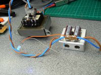
Johnm. The photo below shows a dual secondary tranny. One pair of the ac sec's is connected to one bridge and the other set of ac secondary's to the other bridge. The Bridge Rects are marked + & -, these are the dc outs. the terminals in the opppsite corners are connected together to provide the 0v voltage ref
http://i73.photobucket.com/albums/i239/saxonsex/DualBRect.jpg
In the second picture I use a CT tapped tranny and only one Br Rect. This is simpler in that the two dc outs are marked +& - and the ac goes to the other two. The CT is connected to direct to the power ground.
http://i73.photobucket.com/albums/i239/saxonsex/SingleBridgeRect.jpg
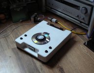
shigaclone
Hi got mine up and running today -will allow burning in-unable to get GB from OZ and M Percy is not responding
So far upgrade power supply with full bridge rectifier-Mundorf power cap
all caps are replaced with Rubycon ZA/ZL/ZLG series
dig out-75R/75R
So far so good.
Hi got mine up and running today -will allow burning in-unable to get GB from OZ and M Percy is not responding
So far upgrade power supply with full bridge rectifier-Mundorf power cap
all caps are replaced with Rubycon ZA/ZL/ZLG series
dig out-75R/75R
So far so good.
Thanks Puffin / Kevin
I'm clear now - I'll twist together the two wires in the 'center' for the CT, and - as Peter said - this will go directly to the negative of the first PSU cap.
The 'outer' 0v and 12v on the transformer will goto both AC points on Peter's PSU board.
I will be using the PSU board with only two diodes as shown in earlier pics.
Thanks,
- John
P.S. Just to avid confusion, both the JVC and the 16v torroidal I used were both single secondaries only, and for those I used four diodes. For this new dual secondary (2 x 12V) transformer I just use two - correct?
johnm said:Thanks Puffin / Kevin
P.S. Just to avid confusion, both the JVC and the 16v torroidal I used were both single secondaries only, and for those I used four diodes. For this new dual secondary (2 x 12V) transformer I just use two - correct?
That's right. With the centre tap configuration, only two
diodes are require.
Dennis
P.S. You guys are really quick on this project; I've had the
boombox for a week and haven't even taken it apart yet.
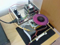
audio1st said:Here's a picture of one of my power supplies. For the JVC I used dual 9V secondaries on a toroid. Keeps the voltage reg' nice and cool.
Hello ,
what diodes are you using in that PS ?
Directions for use with RCEZ32 Only!
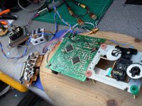
The picture above shows which parts and connectors to remove from the micro-controller board.
This picture shows where to make the connections to the micro-controller pcb. Be extremely careful as any mistakes may result in a RUINED micro-controller. The micro-processor on this board is a mask programmed part which was available to OEM users only, and is now discontinued.
Note the red wire in the foreground left this is 12V_SW, directly behind is the red/black wire which is power control.
This picture shows the location of the wire used to power the led. Cut jumper on other side of the pcb at this location.
Please ring out and verify connections using audio board and psu before making modifications. Be extremely careful, I cannot be held responsible for mis-wiring or mistakes in these directions. (I've tried to make them as clear as possible.) Use at your own risk!
An externally hosted image should be here but it was not working when we last tested it.
The picture above shows which parts and connectors to remove from the micro-controller board.
An externally hosted image should be here but it was not working when we last tested it.
This picture shows where to make the connections to the micro-controller pcb. Be extremely careful as any mistakes may result in a RUINED micro-controller. The micro-processor on this board is a mask programmed part which was available to OEM users only, and is now discontinued.
Note the red wire in the foreground left this is 12V_SW, directly behind is the red/black wire which is power control.
An externally hosted image should be here but it was not working when we last tested it.
This picture shows the location of the wire used to power the led. Cut jumper on other side of the pcb at this location.
Please ring out and verify connections using audio board and psu before making modifications. Be extremely careful, I cannot be held responsible for mis-wiring or mistakes in these directions. (I've tried to make them as clear as possible.) Use at your own risk!
Attachments
- Home
- Source & Line
- Digital Source
- Finally, an affordable CD Transport: the Shigaclone story