Puffin said:Johnm. You say
"You will need to attach two wires to the PSU to get the LED working though, but this is in Okapi's PDF. Have you got the latest version of the PDF by the way? That one shows the LED attachment."
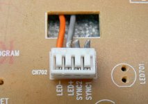
My investigations led me to believe that the voltage for the backlight was only 5v. Am I wrong and wil 8v do it ? There are 4 wires to the display, are only two required and if so what do the other two do ?
There is a resistor value in the PDF that will drop the voltage.
Puffin said:Yes, I see a 10k wired in parallel ? To which two of the four wires does this go. I am not at home right now so cannot look at it, it may be obvious, but if yuo can help ?
Hello Puffin, it is a bit obvious, LED+ & LED-
") ..10k in series with LED+..(grey)..
..10k in series with LED+..(grey)..Attachments
Audio1st. Yes, obvious now ! They now say that drinking as little as 2 glasses of wine a day can lead to early onset Alzheimers. Bring on the men in white coats !
The pdf from Okapi seems to suggest (oddly) that the current limiting resistor sits between the two wires. Or is it the wine again ?
The pdf from Okapi seems to suggest (oddly) that the current limiting resistor sits between the two wires. Or is it the wine again ?
JC951t said:Hi Guys,
Is the EZ37 suitable for this ?
Can't find any EZ31.
Exterior it looks the same though.
Thanks
Hi,
The only reference I found to this machine is here:
http://www.shopnzip.com/product_info.php?products_id=5082&osCsid=92c
If it really plays mp3's then at lease some of the chips are
different and it may not be what you want.
Dennis
I got my RC-EZ31B today, from germany.
There are still four pieces available, on www.amazon.de/JVC-RC-EZ-CD-Radio-Re...bs_sr_1?ie=UTF8&s=ce-de&qid=1208447315&sr=8-1
Delivery only in Germany.
And in Switzerland, you can find another shop, Media Sky:
http://www.mediasky.ch/shop/detail.php?id=15878
Maybe, they send to US?
O.K., I know: the highprice island Switzerland, bad exchange rate for the US$ and shippment cost.
Kind regards
Franz
Tolu said:Hi pros
how does the EZ31 sounds with the internal DAC? Anyone tried it with external (pre-)amp?
What DAC is used in the JVC?
That works fine. The LC78601 is a multipurpose chip, with a build in DAC.
You can extract the line-level signal from the connector/leads on the mainboard that comes from the CD board. The signal leads can be cut and connected to a pair of RCA's placed at a convenient spot. The board says CD-R and CD-L so it pretty easy. You have to retain the GND connection, though. I simply cut the GND lead and soldered it back together with an extra lead soldered to the RCA's.
Sounds pretty descent.
Attachments
Hi everyone.
Well after over 24 hours of running in I was alternating between being happy, and then not sure whether I was getting an improvement or not!!!
The sound was alot more refined and controlled, but I'd lost the excitement and the amazing dynamic ability/speed and THAT bass which I was raving about with the stock mechanism.
Thankfully I managed to rescue the original capacitors from the bottom of our bin (NOT a nice job!!!), and soldered in the original 0.1uF electrolytic. I also glue-gunned down the new crystal to prevent vibrations.
I don't know what exactly it is about this cheap 0.1uF cap, but there's obviously a synergy going on here with the circuit. Have got the excitement back again, as well as the benefits of the upgraded power supply.
So in conclusion I'd say think VERY hard before replacing that 0.1uF cap - any improvement is likely to be a sideways move...
However the PSU mods are WELL worth it - thanks Peter, and Okapi for the PDF guide
Cheers,
- John
johnm said:
So in conclusion I'd say think VERY hard before replacing that 0.1uF cap - any improvement is likely to be a sideways move...
What cap did you replace the original with?
Got mine up and running tonight. The Bass is phenomenal. I will let it run in before I decide to do any other mods. Johnm, with the experience you have had, what, if anything would you reccommend changing on the motor board.
Have you done the 75/75ohm resistor mods to the Dig Out. I haven't done them yet.
Have you done the 75/75ohm resistor mods to the Dig Out. I haven't done them yet.
It's bass is superb isn't it - I could scarcely believe it when I heard it - bass as articulate as a GOOD turntable. Would would have thunk it
I am currently using Peter's recommended 75 / 75 ohm combination for the digital output, though I think I will revert to my original set up, which was one half of an old Audioquest Topaz interconnect cut off, and connected directly to the transport with NO resistors, the other end plugged directly into my DPA DAC.
If you wish to go 'by the book' then apparently the resistor combination should be 291 for series, and 100 ohm for shunt. Shigaraki uses 200 Ohm, with 75 ohm shunt.
I'll give the 75/75 combo another few days, then will revert to no resistors.
- John
Edit: as for the mother board, I'd follow what Okapi has written, but leave that C906 (0.1uF) in place
Update: Changed out the stock transformer, for my 16V 46VA torroidal one. Seems to be running fine. The heatsink is very warm, but it seems stable. I believe the LM4808 has protection circuitry at any rate, just in case. However it's been running for over an hour constantly and seems fine.
Too early to tell any obvious advantages over the original as yet...
Too early to tell any obvious advantages over the original as yet...
If you search back a couple of pages (I think) you'll see a list of what I changed. Just follow that with the exception of the 0.1uF. Sorry I;m too tired to write the whole thing out again, and I can't refer to the mother board any more as I am currently listening to it
Good luck!
Good luck!
Well my latest victim (another RCEZ32) just arrived, I'll be picking it up at the post office.
I'll make all the mods to the controller board and mount everything on the chassis plate over the next few days. I was very happy with the performance - had not finished tweaking, but the installation of BG in selected locations was definitely helping. I have not messed with the tracking servo cap yet. Caps are located in different places on this board.
I will publish my implementation information once I am sure I have something that can be replicated.
I was looking at the schematic of the RCEZ31 and C906 is a capacitor that sets the tracking servo time constant, presumably in the design of the chip the esr of the typical cheap electrolytic is taken into account to arrive at the desired time constant/filter Q. You can use a better quality cap here and by adding a small amount of series resistance reduce the cap's Q in a controlled fashion which might give the best overall compromise. Smaller values such as Peter used might also have a beneficial effect on loop behavior.. This is relatively low frequency stuff so you could run a short pair of wires and tweak until you are happy with the result. The long term stability in performance that you will gain from this approach is worthwhile - I wouldn't expect those cheap parts to maintain their specs over the useful life of this mechanism.
- Home
- Source & Line
- Digital Source
- Finally, an affordable CD Transport: the Shigaclone story