BMW850 said:Problem solved
It was a stupid fault from me, I used a print kroonsteen I don’t know the name in English so see the picture.
One pin is connected to the + and the other to the – to the board that is good, bud under need the board I connect the – from the print kroonsteen also to the – that was the problem, no power to the motor
Rudy
terminal block
")
Puffin said:
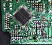
I have only just got around to fitting this clock. Audio1st, it is exactly the same as yours. I have connected it as advised (post 1495 page 60) and it is not reading the TOC and no movement at all from the laser or motor.
From the photo you put on of your clock in situ, it would appear that one of the wires (ground?) is not connected at the terminal block?
There is an OUT and a GRD. I have connected the OUT to the pad you marked XO on your diagram and the GRD to the pad next to it (middle pad of crystal)
Any ideas?
Hi Puffin,
Connect clock "out" to XO. (as you have).. then..
If you use a separate power supply for your clock, then connect clock "Gnd" to the centre pin of crystal location. If your clock shares the same PS as the transport, then you don't need to connect the Gnd clock terminal, (it may cause ground loop problems).
Have you removed the crystal?
Have you reconnected the laser ribbon?
Attachments
I have an issue with both transports that I have. From time to time the transport will skip just a tiny bit. A couple of notes. I can back up and play the same passage again with no problem. I swapped out the first transport but the second is doing this also.
My theory is that it is slop in the gears that drive the sled. I'm hoping something like the weight on a pulley that Eric once used might help counter this by keeping tension pulling away from the spindle.
Does anyone have another idea as to what may be going on?
This little cdp is starting to open up nicely.
When I built my second one, I had that problem. Sometimes it would read the TOC and other times it wouldn't. I "thought" the gears had more slop than the other spares I had here. When I subbed in one of those spares no problems. On my primary shiga, I was getting skips every now and then, and I sprayed a little dry silicone spray lubricant on the rails and the problem went away. Might be worth your while trying that out?
Fran
Fran
Dan_ed said:I have an issue with both transports that I have. From time to time the transport will skip just a tiny bit. A couple of notes. I can back up and play the same passage again with no problem. I swapped out the first transport but the second is doing this also.
My theory is that it is slop in the gears that drive the sled. I'm hoping something like the weight on a pulley that Eric once used might help counter this by keeping tension pulling away from the spindle.
Does anyone have another idea as to what may be going on?
This little cdp is starting to open up nicely.
Dan_ed - i have a similar problem and i will try to solve it by using weights like Eric did... i also think that Fran pinpointed our problem correctly and that this is caused by some dust or something on the sled where laser is sliding.....
.....
try using 1gr or 2gr of weight.....
Tripmaster said:Guess what? I also experience the same fault
I'm not sure weights are going to necessarily solve this problem
weight will make laser run smother on the iron sled... i supose....
Dan_ed - be careful with the lubricant not to make things worse... bad lubricant or to much of it (i supose) can make things worse....
Puffin said:It is a Yes to all your points. I will check the ribbon cable (which is still attached) as I seem to remember I had probs with this before.
Still no luck!
Audio1st. I suppose it is possible that the clock board is faulty. Is there any way to measure if the on-board crystal is getting juice and is actually outputting a signal?
Puffin said:
Still no luck!
Audio1st. I suppose it is possible that the clock board is faulty. Is there any way to measure if the on-board crystal is getting juice and is actually outputting a signal?
Of course there is.. You will need a SCOPE..
This site might actually help: http://www.doctronics.co.uk/scope.htm - should be enough to give you the basics on how to use your scope, and it is humorous too.
Also look for various of the old Tektronix training manuals, they explain how to do various measurements with a scope and are often written for the first time user. At one time they had some of them as pdfs on their site as a historical curiosity.
Hopefully your scope came with a manual and may have some tips on usage.
First let us know what kind of scope you have, it needs to be fast enough to see the clock waveform.. A 20MHz scope will be just serviceable for this task, anything slower really isn't going to be fast enough to look at the ~11MHz clock signals.
I am assuming you will have a 10X probe. (1X probes often have too much capacitance and that in conjunction with the scope's input capacitance makes for poor high frequency performance with many DUTs. ) Calibrate it as discussed in the scope manual or training manual.
Obviously the probe ground goes to a board ground (keep the wiring very short as these are high frequencies) the tip will be used to probe any signal you want to look at.
The clock amplitude is typically around 5V at the input to the dsp chip, so look at it there and set the vertical sensitivity to either 5V/Div or 2V/Div, ((with non auto-ranging probe set to 500mV/Div, or 200mV/Div) trigger on "auto" and horizontal time base perhaps 50ns/Div. If your clock is working and your scope is fast enough you should see a nice squarewave.
Kevin. I have a Velleman HPS10 (see link)
http://www.velleman.be/ot/en/product/view/?id=348271
http://www.velleman.be/downloads/0/hps10.pdf
Features :-
10MHz sampling rate
Up to 2MHz analog bandwidth
0.1mV sensitivity
5mV to 20V/div in 12 steps
200ns to 1hour/div time base in 32 steps
Full auto set up
Trigger mode
etc etc
http://www.velleman.be/ot/en/product/view/?id=348271
http://www.velleman.be/downloads/0/hps10.pdf
Features :-
10MHz sampling rate
Up to 2MHz analog bandwidth
0.1mV sensitivity
5mV to 20V/div in 12 steps
200ns to 1hour/div time base in 32 steps
Full auto set up
Trigger mode
etc etc
Puffin said:Kevin. I have a Velleman HPS10 (see link)
http://www.velleman.be/ot/en/product/view/?id=348271
http://www.velleman.be/downloads/0/hps10.pdf
Features :-
10MHz sampling rate
Up to 2MHz analog bandwidth
0.1mV sensitivity
5mV to 20V/div in 12 steps
200ns to 1hour/div time base in 32 steps
Full auto set up
Trigger mode
etc etc
Afraid that you may not see much with that.
You will need unit at least 30Mhz and up for measuring in this this digital area.
Hi there,
Just an amazing thread that is!!
you got me searching for 51 model, so i got two to get me started.
So is it a good way to start with what Peter and OKapi suggested in the first postings?
Any reasonable clock, or the crystal that Peter suggested does the job after all?
Maybe i am asking the same things with others but the postings here are just extraterrestrial in volume to read.
Anyway i read most but i got lost hehe so i thought i just ask
Thanks Peter and others here for the wonderful contribution in the DIY.
tiglitosa said:
Any reasonable clock, or the crystal that Peter suggested does the job after all?
My suggestion is step by step approach. Start with the stock board and the power supply.
Read this post of Peter Daniel, it's useful.
http://www.diyaudio.com/forums/showthread.php?postid=1479165#post1479165
tiglitosa said:Hi there,
Just an amazing thread that is!!
you got me searching for 51 model, so i got two to get me started.
So is it a good way to start with what Peter and OKapi suggested in the first postings?
Any reasonable clock, or the crystal that Peter suggested does the job after all?
Maybe i am asking the same things with others but the postings here are just extraterrestrial in volume to read.
Anyway i read most but i got lost hehe so i thought i just ask
Thanks Peter and others here for the wonderful contribution in the DIY.
Well, I did read the thread before starting on a Shigaclone myself and what I learned from that is that there is no "golden rule" or clear cut way to do the upgrade. It also depends on other variables than just the mechanism itself. In other words: everyone ends up with a different Shigaclone.
You can see okapi's pdf as a guideline at most. I implemented it partly, but I have already decided not to stick to it closely anymore.
If you skim through the thread you will see two extremes (and everything in between). Notable are an only slightly modified version (Peter's second 'clone) and a state-of-the-art version wich costs about the same as a small car (Erik's version).
My take on it is as low cost as possible. That excludes exotic materials, but I believe if you get the basics right, then most "improvements" from that point on are mostly psychological. This belief works great for me because it simplifies things a lot.
I’ve definitely finished my clone. It sounds better than everything I heard before, including several clone versions.
No exotic parts, just very pragmatic/engineering approach with the schema (A0 plotted and LC78601 n LA9242 n LA6541 data sheets in hand.
The clue is to provide well separated and noise-free power to each of 3 “main” Vcc of LC/LA combo, and Vref too. LA6541 is supplied separately, as well as external clock.
The parts used are 3 LT1117 stabs being put directly to pcb, some tantals and inductors. Some of original caps and resistors are removed.
The total cost of clock, trafos, PSUs, stabs, etc. is ca. 150$.
No exotic parts, just very pragmatic/engineering approach with the schema (A0 plotted
and LC78601 n LA9242 n LA6541 data sheets in hand.The clue is to provide well separated and noise-free power to each of 3 “main” Vcc of LC/LA combo, and Vref too. LA6541 is supplied separately, as well as external clock.
The parts used are 3 LT1117 stabs being put directly to pcb, some tantals and inductors. Some of original caps and resistors are removed.
The total cost of clock, trafos, PSUs, stabs, etc. is ca. 150$.
- Home
- Source & Line
- Digital Source
- Finally, an affordable CD Transport: the Shigaclone story