Hey Chas,
I considering modding my 2900 and was going to do it in stages.
In your opinion what gives the most bang for the buck?
Power supply, op/amps or clock change.
I'm also wondering if descrete op/amps are worth the investment.
Is there any recommended reading or links that might have some step by step instructions and good pictures and part value recomendations( I have read that many increse the cap values in the P.S. above the stock values).
Thanks for all your insight so far Chas!!
Keep up the good work!!
rtate,
Check out this thread on DVD2900 tweaks.
http://www.diyaudio.com/forums/showthread.php?s=&threadid=42436
Several people, more knowledgeable than I, have contributed their experiences and opinions. This is what inspired me to undertake the mods I've done.
My opinion is that while you can throw a chunk of money at improving the clock, the power supply and opamps are the weakest link and are more cost effective mods (I caution against large increases in supply capacitance, especially right after the stock regulators finding it better to use qualitycaps and bypasses).
Your first step should be to obtain the service manual if you don't have it already.
The Underwood and SACD mods websites provide useful hints at which components to replace. M. Percy Audio is my personal favorite supplier of kind parts.
Please let me know if you have any specific questions, as I've become pretty familiar with working on this model.
Best wishes and Happy Holidays!
-chas
Thanks Chas
I will take you up on your offer as I have several questions.
However I have not even popped the cover on my 2900 yet so most of my questions are still pretty general at this time.
I do have a copy of the service manual but I find the schematics hard to follow
I will be using the 2900 for 2 channel Audio only sacd, dvd-a and redbook formats. so I will only want to modd the front channels and power supply at this point.
How many op/amps are in the stereo signal path?
I am not sure about which op/amp subs to use yet.
they all seem to have different flavors and I'm not sure if the discrete op/amps will fit comfortably......
So I will be researching this and soliciting opinions from all!!
I also see a wide range of diodes for the power supply. I am not as concerned with cost as I am size and performance.
Is there a "good, better, best" for diodes as far as part #'s and manufacturers go?
How many op/amps are in the stereo signal path?
There are 6 dual opamps in the stereo signal path(2 for I/V conversion, 2 for the fillter, and 2 more for the output stage).
I'm not sure if the discrete op/amps will fit comfortably
If the video PCB is retained, there isn't enough vertical clearance for discrete opamps such as the Burson units. I'm using a pair of OPA627's on a Brown Dog adapter in place of each OP275op (8pinDIP) used for the right and left outputs.
While the the stock diodes work ok (what comes after the SMPS seems to have more of an effect on the sonics), use ofIs there a "good, better, best"... diodes for the power supply...?
the Fairchild "stealth" diodes (from Percy Audio) would be an improvement over stock.
The diodes I chose are the ON Semi MUR860 8A 600V FRED's from Partsconnexion(and they're currently having a sale).
-chas
While I only plan on using the 2900 for 2 channel audio, I'm not sure that i want to remove the video portion of the player.
If I were certain that the discrete op/amp would make a HUGE difference I might consider it....
Parts connexion is a 5 minute drive from my place and I am there quite often...
If I were certain that the discrete op/amp would make a HUGE difference I might consider it....
Parts connexion is a 5 minute drive from my place and I am there quite often...
I prefer the AD826AR SOIC for I/V conversion and the OPA627AP/BP 8PDIP for the outputs. 826's are better suited for I/V conversion than the stock units, and I just prefer the sound of the OPA627's at the outputs.Are different op/amps better for different positions i.e. output vs. I/V and whch opamp is your preference now and why?
I read somewhere that the suffix on the opamp can mean better tolerance? Can you confirm this?
The OPA627BP is supposed to be better than the AP version, but the only difference I can see from the data is that the BP has slightly better DC-specs(which shouldn't matter here).
Did you bypass the +v/-V on all op/amps?
I bypassed all the reservoir caps on the Audio board, and used local bypasses at the supply pins of the OPA627's.
Did you bias the opamps to class A and if so were there audible benefits. Also how do you accomplish this?
I did bias some of the opamps into class-A, using "pulldown" resistors from output to V- pins. Many, including Walt Jung, say this improves the sound. I believe I can hear a difference.
Did you experience any “clipping” with the new op/amps?
None that I could detect.
In the smps are the FRED diodes the best to use or are there better?
Since they are before the SMPS(and it's what comes after the SMPS which makes the most audible difference), FRED's should be more than good enough.
Have you considered upgrading the regulators in the p.s. to some sort of super-regulator?
I considered it; however, most of the super regulators I'd found were either physically too large, or they wouldn't handle the current requirements of the entire audio PCB. My solution was to use a small 3.3v "super" regulator in place of the stock 3 pin job on the PCB for the L/R channel D/A converter chips.
For the resistors in the signal path,what sort of rating did you use??
I used 0.5W Riken Resistors, since these are what Underwood Mods recommended.
Since the Video PCB merely unplugs, you can always replace it later if you want to restore this function; Of course, you can always experiment with the "Pure Direct" mode to turn off the video circuitry if you want to evaluate its effect upon audio sound quality.I'm not sure that i want to remove the video portion of the player.
I hope the above is helpful.
Good luck in your mods and Happy Holidays to all!

-Chas
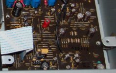
Do you remember what the location of the 3.3v regulator that you changed
Yes, the attached photo shows it at the front of the Audio PCB. I believe it replaced IC205.
Is there a how-to somewhere on biasing the op/amps that shows where the pull down resistors go and what values to use?
Just do a search here on "pull-down resistors" or "class-A biasing op amps". The desired bias current and supply voltage determine the value of resistor- I usually shoot for 2-4ma (and "Carlos" here on the boards seems to favor around double that).
Cheers!

-chas
Attachments
what about replacing IC221 as well?
I hadn't found an economical upgrade/replacement for IC221, so I just installed a large value, low ESR cap(w/bypass)at its output.
Since the location of IC225 lies beneath the video PCB, we're back to the physical size vs current capacity issue here...
Other than L909, which was replaced with the 330uH choke, I left the stock inductors alone (except I did add a wideband "bead on a lead" at position FB211) and replaced some of the local bypass caps with BlackGate N/NX series.
The AD826 was used for I/V conversion. The stock opamp can be retained for the filter, where it does a decent job; however, I have also used the LM6172 in the filter position. I haven't compared the 8620 et al.....did you use the AD826 for the "filter stage" op/amps as well?
What was the current rating of the reg ...Where did you source it from?
It was an Audiocom 3-pin regulator PCB assy, similar to the UWB from Dexa "new Class D":
http://www.newclassd.com/index.php?page=70
I am having trouble findind a 220 uf400v cap for the power supply after the diodes.
I prefer the Black Gate 150uf/350v VK cap from M. Percy Audio.
I hope this helps.
-chas
Check the Service Manual
The I/V stage IS the first pair of NJM2068 IC's (dual opamp used in differential mode)on the audio PCB.
For any specific IC numbers and locations on the PCB, please check the service manual.
-chas
p.s.I will be undergoing surgery in a few days, and will be unavailable until January.
The I/V stage IS the first pair of NJM2068 IC's (dual opamp used in differential mode)on the audio PCB.
For any specific IC numbers and locations on the PCB, please check the service manual.
The 150uf/350v works just fine; however, I wouldn't recommend going below a 350wv rating.would the Black Gate 220uf 200v work or is the voltage rating too low?
-chas
p.s.I will be undergoing surgery in a few days, and will be unavailable until January.
about biasing the op/amps to class “A “, Do you think it made a big difference/was it worth while?
Yes. Both filter and output opamps were biased into class-A and felt there was a noticeable improvement. From the reading I'd done, I saw no reason to change the bias on the I/V stage(the AD826's installed there were just fine as-is).
I used whatever was on-hand, likely 22nf-33nf or so(some people prefer BG 0.1 NX's).The bypass caps on the opa627’s look like polystyrene, what value did you use?
Yes. For each local bypass I replaced the ceramic chip cap with a 10 or 100nf cap(usually BG NX).Did you remove the smt chip capacitors around the output op/amps(c343,344,345 and 346);If so did you remove any other components ?
No. I prefer to use the bypasses as close as possible to the opamps(since there is all that power supply wiring that connects the PS board to the Audio board). If I remember correctly, I used 0.47 bypasses at C220/C221, C349/C354, and 0.1's elsewhere.Back to the power supply...Did you use any .47uf bypass caps under that board?
If you read these threads, you will find many answers(as I did):
http://www.diyaudio.com/forums/showthread.php?s=&threadid=42436&highlight=
http://www.diyaudio.com/forums/showthread.php?s=&threadid=37669
http://www.diyaudio.com/forums/showthread.php?s=&threadid=47029
http://www.diyaudio.com/forums/showthread.php?s=&threadid=53804&perpage=25&highlight=&pagenumber=1
http://www.diyaudio.com/forums/showthread.php?s=&postid=1472200&highlight=#post1472200
Please share your progress and results here, so that others may benefit.
-Chas.
When by-passing the op amp I have seen 3 methods and I 'm not sure which will work the best for me.
On the opamp data sheets I have seen
1) by-passing from both the + and - pins to ground
2)by-passing across the + and -
3)combining both methods above(used by Chas!!)
I would like to know what the differences are between the methods(hopefully Chas is watching )
On the opamp data sheets I have seen
1) by-passing from both the + and - pins to ground
2)by-passing across the + and -
3)combining both methods above(used by Chas!!)
I would like to know what the differences are between the methods(hopefully Chas is watching
)On the audio board the schematic has c242 as "open" however in your picture there is a electrolytic there;Why did you put a cap there, and what value did you use??
I simply removed the .01uf SMT ceramic across Vcc and installed a 0.1uf Black Gate NX-H in the corresponding location provided.
The 0.1 NX-H has been highly recommended (by several respected modders) as a bypass on the voltage pins of the DAC.
Best wishes on your mods. I can't wait to see your pics.
Regards,
-Chas
- Status
- This old topic is closed. If you want to reopen this topic, contact a moderator using the "Report Post" button.
- Home
- Source & Line
- Digital Source
- Comparison of Denon DVD-2900 Mods