Hi.
Any idea for a quick fix on the Mosaic. Would like to use the integrated headphone-amp via the variable line output. BUT i don't have the fitting remote for the volume control at hand. Since playing via my RasPI/NAS with LINN Kazoo as controller there is no chance to do volume via software...
What about using an universal programmable remote? Which IR codes would do the trick VOL+ and VOL- ?
Cheers
Bernie
Dear all
I've removed the output protect and the "kill" circuit
Direct out after the output Cap.
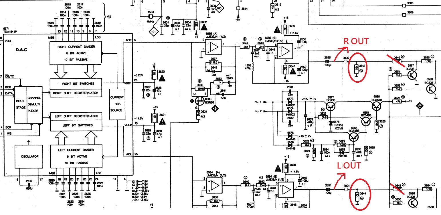
Do somebody know if I can move the output 10K shunt Resistor(3645 3644 ) or not?
Maybe it's related to the impedance matching with the AMP
My AMP is JC Verdier 220de(6L6G)(with 16W output and 50K VR input)
I've removed the output protect and the "kill" circuit
Direct out after the output Cap.
An externally hosted image should be here but it was not working when we last tested it.
Do somebody know if I can move the output 10K shunt Resistor(3645 3644 ) or not?
Maybe it's related to the impedance matching with the AMP
My AMP is JC Verdier 220de(6L6G)(with 16W output and 50K VR input)
Last edited:
It is a high pass filter but that is not its function. It is always good practice to terminate a capacitor coupled output into a ground referenced resistor so that the output voltage is precisely determined (0.00 volts DC). Without the resistor the output floats and could assume a DC voltage depending on the equipment it is connected to.
It also precisely determines a zero volt condition for the muting transistor operation. Any slight residual DC voltage would cause loud thumps when the muting operates.
It also precisely determines a zero volt condition for the muting transistor operation. Any slight residual DC voltage would cause loud thumps when the muting operates.
The output impedance is low and mainly determined by the series resistance from the cap to the socket. It is good practice to always keep a minimum of at least 47 ohms to protect against possible capacitive loading from causing instability in the opamp.
The resistor to ground should be low enough to charge the cap quickly. Removing the muting means that no value will eliminate switch on/off noise completely.
The cap and resistor should be chosen such that the LF response is maintained (remember to include the external impedance the output stage works into as well)
Ya it sounds reasonable.
Thanks for all your feedback!
Any suggestions for the value of resistor?
I’m not so sure about the theory about the impedance matching between the
Amp and cd
Function is indeed HP filter, to say otherwise is to ignore its function. Static value is meaningless, the working value will be the value of this resistor in parallel with the input impedance of the following stage which is 50,000 ohms. Leave it as is, or increase to 1M. If you increase it to 1M, you can reduce the value of the capacitor. Theory for impedance is simple, use a source with an output impedance which is less than 0.1 times the input impedance of the next stage. In your case 5,000 ohms, and the capacitive reactance of the cap will present some impedance at low frequencies but benefit of using 2.2u film over 100uF electro would in my opinion take precedence. Either way, situation is fine.
Last edited:
Ya it sounds reasonable.
Thanks for all your feedback!
Any suggestions for the value of resistor?
I’m not so sure about the theory about the impedance matching between the
Amp and cd
Function is indeed HP filter, to say otherwise is to ignore its function. Static value is meaningless, the working value will be the value of this resistor in parallel with the input impedance of the following stage. You have said that this is 50,000 ohms. Use 1M.
")
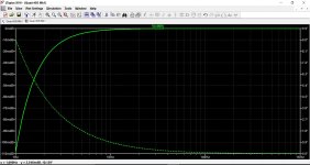
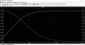
What you use depends on what you are feeding it into. This shows the low frequency response of the 100uF and 10k followed by 2.2uF and 10k.
Philips would use the most cost effective part for the job and that would be a largish electrolytic.
Philips would use the most cost effective part for the job and that would be a largish electrolytic.
Attachments
What you use depends on what you are feeding it into. This shows the low frequency response of the 100uF and 10k followed by 2.2uF and 10k.
......
Sorry....maybe this is a silly question.
Why do I need a suppression at low frequency?
Exactly.The HPF pair 2.2uF 10K has a cut of frequency at about 8Hz nearly into the audioable region.
So my question is why not keep the 100uF?
What’s the benifit about changing to 2.2uF?
The difference between film and electrolytic?
It is about the phase. 10K is for 10uF 22uF C before. 2.2uF causes larger phase shift. 100uF is too much...
.
Ideally the target is -0.25db at 20Hz, -7deg cca.
so that is about 1.6Hz -3db and that Fo is required for the filter cutoof.
- Home
- Source & Line
- Digital Line Level
- Building the ultimate NOS DAC using TDA1541A