Thanks. I dont think it will be easier for me to translate what you have done here to glue logic in the traditional meaning. It seems to me I have to use a lot of logic devices to generate the different singnals shown in your scheme. And I don´t want to use MCK.
DATA, Word clk and Bit clk is sufficient.
But thanks anyway and I am sorry for my ignorance when it comes to cpld.
DATA, Word clk and Bit clk is sufficient.
But thanks anyway and I am sorry for my ignorance when it comes to cpld.
Your welcome, we´re here to learnBut thanks anyway and I am sorry for my ignorance when it comes to cpld.
Any thoughts on sound quality vs Ian's I2S2PCM approach?
Hi Walter,
When it was first powered up and running I noticed straight away that it sounded different. After some critical listening I can say that the sterreo image has changed. Sources of sound in the soundstage have become more pronounced to their position, bringing with it a more realistic musical representation. Symbols have more sparkle, vocals bring with them more of a feel for the space they are in and bass has more authority.
The differences are subtle, but they are definitely there. YMMV.😉
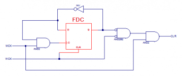
I came up with this neat circuit in case WCK has to be an input. It makes a pulse with the falling edge of WCK, the duration of which is half the MCK period (provided that WCK and MCK are in sync). Use it to reset a counter (or cascaded counters) with asynchronous clear. If you do it right then the counter will be in phase (Q7 will coincide with WCK if MCK is 256FS).It has only two inputs: MCK_IN (at 256FS) and DATA_IN. The rest are outputs
(BTW the 74HC74 has active low clear, unlike the Xilinx macro, adapt as needed).
-Alex
Attachments
Hmmm, just realized that it might produce an undesired spike and thus a second asynchronous clear with the rise of MCK.
edit: I think it may work if I add just the right amount of capacitance at the output.
edit: I think it may work if I add just the right amount of capacitance at the output.
Last edited:
I attached a schematic diagram of an I2S to Simultaneous converter for the TDA1541A.
The circuit performs following functions:
- Identify and invert MSB within the serial data stream.
- Delay the left channel data in order to align it with the R channel data.
- Create a 16 bit window for clock and data output signals.
Timing diagram is added at the bottom.
The circuit can be built with logic building blocks like 74HC, 74 AHC, 74LV, 74LVC.
If U13 is a problem one can combine two 74HC86 XOR gates instead. One output goes to one input of the other XOR gate, we now have an XOR gate with 3 inputs and one output. The 74LVC1G386 is available in SOT32-6 housing:
http://www.ti.com/lit/ds/symlink/sn74lvc1g386.pdf
Depending on logic building block properties the circuit can work on voltages between 2V4 and 5V. I recommend to use 2V4 ... 3V3 supply voltage.
Connections:
I2S,
DI = D
WSI = WS
BCKI = BCK
Simultaneous,
OB/TWC (pin 27) connects to -5V to put the TDA1541A in simultaneous mode.
DOL connects to pin 3
DOR connects to pin 4
BCKO connects to pin 2
LE connects to pin 1
LE determines the exact moment of output latching, output latching occurs at the 0 -> 1 transition (TDA1541A set to simultaneous mode).
BCK clocks in the data on the 1 -> 0 transition (TDA1541A set to simultaneous mode).
Hi John,
Does this support 24 bit data? I also need inverted data for a balanced DAC. Will two boards and swapping some components work for balanced?
Thanks

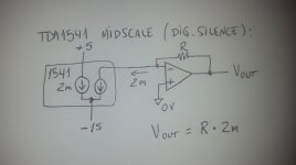
I can hardly see anything there (I'm on the phone and I cannot magnify it), but more than likely it is a biasing circuit with RC filter built-in. TDA1541(A) can only sink unipolar current from 0 mA to -4 mA. Such circuit injects a DC current of 2 mA resulting in a final bipolar swing of -2 mA to 2 mA, so no capacitors are required to remove the DC offsets normally introduced by the DAC itself.
Hi John,
Does this support 24 bit data? I also need inverted data for a balanced DAC. Will two boards and swapping some components work for balanced?
Thanks
This circuit does only clock-in 16 bits of data and it operates in stopped clock mode. It is useless for any other non 16-bit DAC.
This circuit does only clock-in 16 bits of data and it operates in stopped clock mode. It is useless for any other non 16-bit DAC.
Thanks
I can hardly see anything there (I'm on the phone and I cannot magnify it), but more than likely it is a biasing circuit with RC filter built-in. TDA1541(A) can only sink unipolar current from 0 mA to -4 mA. Such circuit injects a DC current of 2 mA resulting in a final bipolar swing of -2 mA to 2 mA, so no capacitors are required to remove the DC offsets normally introduced by the DAC itself.
Sorry!I still can't understand why do we needs to feed a DC bias into the analog output.
The input is +8V DC with series 2k2R 2k7R and shunt cap 10uF betwenthem
Hi
3lite said correctly that the midscale is not zero milliamps, it is 2mA. Without said circuit the output won´t be centered between the opamp supplies.
However, there is another thing to consider before using the circuit. Some opamps like the old 627 operate better when they are only outputting current. Folks used to put a resistor from output to V- and called it class A bias, others (Bruno Putzeys) explained that something else is happening (better supply rejection when using only one of the transistors of the class AB output stage. Only the NPN in the case of the 627).
So you may be better off without the circuit if your opamp is like the 627. Apparently it has worse +V PSRR, so the trick may apply to any opamp like this (worse +V PSRR).
-Alex
Attachments
Last edited:
Hi Alex:
Thanks for your kindly feedback.I’ve also refer to the other discussion about the same issue on creek cd 60.
My understanding is that seem a compensation with the AOL output current
And keep the OP amp out at 0V
In my knowledge is the OP AMP got high impedence at input
Is this compensation necessary?
But the philips guys do this too
My lately circuit is from the philips cd304mk2
That explain things!!
Thanks a lot!!
But now I’m wondering how this circuit effect the sound
Maybe the soonest way to figure out is to remove it from my 304mk2 NOS then do the comparison
Hi
No, it will work without the compensation. It might work better without it, depending on the opamp.
The opamp output will sit at 2V (positive); the opamp will be always sourcing current, never sinking. Can you see how this is similar to the old trick of resistor to V-?
Thanks
Alex
Hi Alex:
Thanks for your kindly feedback.I’ve also refer to the other discussion about the same issue on creek cd 60.
My understanding is that seem a compensation with the AOL output current
And keep the OP amp out at 0V
In my knowledge is the OP AMP got high impedence at input
Is this compensation necessary?
No, it will work without the compensation. It might work better without it, depending on the opamp.
The opamp output will sit at 2V (positive); the opamp will be always sourcing current, never sinking. Can you see how this is similar to the old trick of resistor to V-?
Thanks
Alex
Hi
......Can you see how this is similar to the old trick of resistor to V-?
Thanks
Alex
Do you mean bias the OP AMP to class A?
- Home
- Source & Line
- Digital Line Level
- Building the ultimate NOS DAC using TDA1541A