The reviewer of "Audio Club Velsen" preferred the DI4MJ (4 x TDA1543) without even knowing what DAC chips were used inside the unit.
What does it tell ? Nothing. Some people prefer Lampizators.
")
I have stopped counting all those quantum leapsThe sound quality of the single TDA1543 in the ISD player made a quantum leap compared to the early DI4MJ and DI4T designs that were driven by an iMac (AE module with Toslink output).
Everything I do is done for good reason, double and triple checked, verified by extensive listening tests. My aim is improving performance instead of degrading it. I started this project in 2006, the ISD player was completed last month. The unit sounds like almost 4 years of extensive research was put into its design.
Still you won't change the linearity issue.
Perhaps you prefer the sonic signature of the 1543 distortion.
It does "enhance" the sound somehow. Same way like the 1540 14bit.
If someone told you a single TDA1543 can create the impression of listening to live sound quality, you would say: impossible, this cannot be, theoretically THD is too high, dynamic linearity errors are too high, it's a economy chip, not designed for these performance levels. You could come up with all kinds of theories and measurements why this cannot be done.
Somehow you block against arguments.
It has nothing to do with "could come up with all kinds of theories and measurements why this cannot be done"
Facts are facts and monks are not DAC chips.
Low level distortion is audible as described.
Barriers are only in the mind, and it's all just a matter of technique.
Phrases do not help.
See it like this:
Not all tones of all instruments and not all voices have lots of harmonics, some are more like pure sines, especially in silent passages.
When your 1543 plays music, during the silent passages the pure sounds are smeared by added harmonics.
So the silent pure sounds are missing, the DAC fails to reproduce them correctly because of the added distortion.
No tricks of implementation will cure it.
The MSB error adds a step at the zero crossing of the signal.
It sounds like a classB amp with very little idle current.
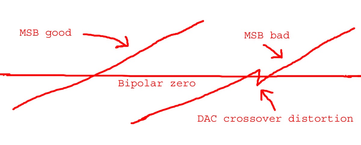
The crossover distortion is always there but it is more or less masked during loud passages because the amplitude of the error is small in relation to the signal.
However, it becomes more and more noticeable on lower levels.
Ignore it if you want
See also here:
http://www.diyaudio.com/forums/digital-source/49778-new-dac-measurement.html
Last edited:
Hi John ( ecdesigns?) , what do you think of pedja discrete output of tda1541, did you ever tried it ? Its only using one tda and it looks neat !http://diy.audialonline.com/archive/I-V-discrete.pdf
Looking for Stereophile-style measurements for non-os (whether it's the one in this project or another non-os).
Example of Stereophile-style measurements for non-os:
Stereophile: Zanden 5000 Mk.IV/Signature D/A converter & 2000 Premium CD transport
Stereophile: 47 Laboratory 4715 D/A processor & 4716 CD transport
P.S.: I have looked over Bernhard's measurements, but I have not searched this thread/forum extensively.
Thx,
-hm
DIY hybrid cap
Hi EC,
Can we build the CAP with multilayer PCB? I guess the cost can offset the labour.
Regards
Hi EC,
Can we build the CAP with multilayer PCB? I guess the cost can offset the labour.
Regards
Hi jstang,
It's basically a Monacor 3.3uF MKT capacitor with a bypass cap made from a euro sized (100 x 160mm) double-sided 0.5mm thick PCB (epoxy) material. because the PCB was rather large, I cut it into 4 pieces and milled / drilled them to form a compact capacitor.
The Monacor cap is inside the packet, mounted on a single-sided PCB with a slot for the capacitor. The PCB material was arranged so I have "outer foil" on top and bottom for screening. The parts aren't very expensive (approx $8 for one cap), but I spent over an hour milling, tinning and assembling these hybrid caps.
It's also very important to check for short circuits and use fine sandpaper to smoothen the PCB edges, removing possible short circuits. If the package has been assembled and you measure a short circuit you have a big problem.
Why on earth use a double-sided PCB as bypass cap?
The copper foils are fused to the epoxy base material (no air pockets). The PCB (enforced with glass fiber) is way more stable than any foil. In other words, this cap has less mechanical resonance compared to a very thin flexible foil.
Bypass caps only work effectively if they have very low self resonance, otherwise you simply add resonances from both, main and bypass cap, making matters worse. This is the main reason why bypass caps usually aren't very effective.
The bypass cap value does not have to be that big, the PCB bypass cap value equals approx. 1.5nF, this is sufficient for a 3.3uF main cap.
The idea is to dampen the main cap resonances, creating better specs than when using only a single (flawed) cap. This $8 coupling cap was directly compared with a V-cap TFTF (switch), and all people who listened to both caps preferred the $8 cap without knowing what cap was selected. The V-cap TFTF is regarded as one of the better audiophile caps and a single 3uF version cost around $699. The V-cap TFTF performance didn't improve significantly when bypassed with a PCB.
I believe that you like the ESS 9018 chip and other simmilars 32bits/384Khz ones. Certainly, the WM8741/42 and so on sound very well, but they lack some kind of "live " sensation. The scope, fft analyser and so, helps with the measures, but the final test is done in the ears, and inside our brain, far beyond the traces of modern instrumentation. For me is an error to fall again in the measures only. for example, not all the 50W amplifiers sound equal, you know. It seems that you are against the TDA dac series. Maybe they have a little noise floor, but the sound it is fantastic. I've bought 4 S2 from Australia, I've tested, and they are incredible with all it's 16 bits.
Best regards,
Best regards,
Yes galeb, as I said earlier I never heard yet a high sampling rate recording played on the new high res dacs, but let me just reiterate that for me the tda1541 specific like they put in the sony 555 etc beat everything I heard, though not in the bass department , sound stage quite same as new dacs, for example the cirus is more virile ( the old bryston dacs , creek, audio research) but the separation and texture of different instrument is top notch, you hear everything and follow any voice with ease,
There is a difference in CLEAR DEFINITE SOUND and just CLEAN SOUND (strained of important content) with poor difference between different instruments playing at same time etc
I don’t know like the Zenden if the sound stage gets wider , I associate this actually with tube that put some harmonics
Hi John ( ecdesigns?) , what do you think of pedja discrete output of tda1541, did you ever tried it? It’s only using one tda and it looks neat !http://diy.audialonline.com/archive/I-V-discrete.pdf
Hi EC,
Can we build the CAP with multilayer PCB? I guess the cost can offset the labour.
Regards
The image of those custom made caps just has not left my mind... I am very interested in what they could sound like....
I was thinking about the multilayer idea, but where do you find Un-etched multilayer boards? Not sure there is a such an off the shelf board....multilayers of un-etched internal copper?
So I guess you could stack several single layer, single sided boards to make your own layers..... and alternated the plates +/-. The last board would need to be a double sided board just to balance out the number of + & - plates.
Would that work? Never built a capacitor from scratch before. Other then walking on a carpet with sweater on and shocking myself on the door knob...
JohnB seems to have used double sided boards with an air gap in between. With nylon screws and standoffs. Then milled the board edges to create a terminal and area of isolation for connecting the plates.
Guess there are more than just a few ways to skin this cat...
jk
Last edited:
Hi jstang,
These custom caps exceeded audiophile capacitors (V-cap TFTF, Duelund, Sonicap, Jantzen) performance, in this specific application:
coupling cap for TDA1543, DC across the cap approx. 2.7V, ac across the cap 1.6Vpp. Cap loaded with 10 ... 50 K Ohm potentiometer.
I used a cheap MKT Monacor cap (eur 1.60) and a euro-sized 0.5mm thick double sided PCB as HF bypass cap (eur 5).
Yes this is possible, 5 layer PCB (1.6mm thick) could replace the 4 separate PCBs with one single PCB the size of 100 x 40mm. These HF bypass caps could even be integrated in the PCB design of a DAC. They could also make super decoupling caps for power supplies.
No this would put air between subsequent plates and introduces resonance again as both PCBs can easily move (resonate) varying the distance between the copper plates. The idea is fusing the copper foils to a dieelectricum, greatly reduciing mechanical resonance and removing as much air as possible between copper sheet and dieelectricum. The air between foils in a foil cap allows the foil to move or resonate. You could try glueing the single sided PCBs together, making sure no air pockets or bubbles get trapped between the PCBs, this however cannot be verified (copper foil prevents checking this). Easiest by far is simply using double-sided PCB material.
The image of those custom made caps just has not left my mind... I am very interested in what they could sound like....
These custom caps exceeded audiophile capacitors (V-cap TFTF, Duelund, Sonicap, Jantzen) performance, in this specific application:
coupling cap for TDA1543, DC across the cap approx. 2.7V, ac across the cap 1.6Vpp. Cap loaded with 10 ... 50 K Ohm potentiometer.
I used a cheap MKT Monacor cap (eur 1.60) and a euro-sized 0.5mm thick double sided PCB as HF bypass cap (eur 5).
I was thinking about the multilayer idea, but where do you find Un-etched multilayer boards? Not sure there is a such an off the shelf board....multilayers of un-etched internal copper?
Yes this is possible, 5 layer PCB (1.6mm thick) could replace the 4 separate PCBs with one single PCB the size of 100 x 40mm. These HF bypass caps could even be integrated in the PCB design of a DAC. They could also make super decoupling caps for power supplies.
So I guess you could stack several single layer, single sided boards to make your own layers..... and alternated the plates +/-. The last board would need to be a double sided board just to balance out the number of + & - plates.
No this would put air between subsequent plates and introduces resonance again as both PCBs can easily move (resonate) varying the distance between the copper plates. The idea is fusing the copper foils to a dieelectricum, greatly reduciing mechanical resonance and removing as much air as possible between copper sheet and dieelectricum. The air between foils in a foil cap allows the foil to move or resonate. You could try glueing the single sided PCBs together, making sure no air pockets or bubbles get trapped between the PCBs, this however cannot be verified (copper foil prevents checking this). Easiest by far is simply using double-sided PCB material.
Hi jstang,
No this would put air between subsequent plates and introduces resonance again as both PCBs can easily move (resonate) varying the distance between the copper plates. The idea is fusing the copper foils to a dieelectricum, greatly reduciing mechanical resonance and removing as much air as possible between copper sheet and dieelectricum. The air between foils in a foil cap allows the foil to move or resonate. You could try glueing the single sided PCBs together, making sure no air pockets or bubbles get trapped between the PCBs, this however cannot be verified (copper foil prevents checking this). Easiest by far is simply using double-sided PCB material.
Understood... But wouldn't bolting the boards together be enough dampen the resonate? seeing that the copper is already bonded to the fiberglass. Or do think that the fiberglass layers will resonate even though they are bolted together.
It would be easier I guess to find a manufacture to provide layered un-etched PCBs.... time to search the web and make some calls....
johnk
But wouldn't bolting the boards together be enough dampen the resonate?
That's on the line of what I asked before: would two plates of wood be useful as forming and damping element? I guess different kind of wood (or fiberglass or else) would resonate at different F, low in any case...if one has the time to try it...
Dear -EC-, maybe a little drawing of the concept cap would be needed to make thinks clear...
Thanks,
M.
I was being lazy...and would rather buy some boards off the shelf... I wonder if someone on this board can provide internally un-etched layered PCBs.
Lazy me will have to start searching.....
jk
Hi jstang,
No it won't, it's essential that both foils are fused to one and the same insulator (Epoxy).
If you bolt 2 pcs of single sided PCB together you will always get air pockets, even when using 135 bolts (9 x 15 bolts) on one euro size PCB. That's why I use double sided PCBs instead.
The aim is to maintain absolute constant distance between both (copper) foils, regardless of material resonances. This way the capacitance doesn't change at all when the material resonates.
So instead of attempting to minimize material resonance, I made sure material resonance won't have any effect on capacitor performance.
I got the PCBs from Conrad Electronics, these PCBs have photo sensitive lacquer on both sides, this lacker comes in handy to prevent oxidation of the copper foil.
Understood... But wouldn't bolting the boards together be enough dampen the resonate? seeing that the copper is already bonded to the fiberglass. Or do think that the fiberglass layers will resonate even though they are bolted together.
No it won't, it's essential that both foils are fused to one and the same insulator (Epoxy).
If you bolt 2 pcs of single sided PCB together you will always get air pockets, even when using 135 bolts (9 x 15 bolts) on one euro size PCB. That's why I use double sided PCBs instead.
The aim is to maintain absolute constant distance between both (copper) foils, regardless of material resonances. This way the capacitance doesn't change at all when the material resonates.
So instead of attempting to minimize material resonance, I made sure material resonance won't have any effect on capacitor performance.
It would be easier I guess to find a manufacture to provide layered un-etched PCBs.... time to search the web and make some calls....
I got the PCBs from Conrad Electronics, these PCBs have photo sensitive lacquer on both sides, this lacker comes in handy to prevent oxidation of the copper foil.
Got you...and thanks very much as always.....
Double sides boards are no problem for me to source.... un-etched Multilayer ( 4 or 5 copper layers ) is a different story for me....
jk
Double sides boards are no problem for me to source.... un-etched Multilayer ( 4 or 5 copper layers ) is a different story for me....
jk
Hi jstang,
No it won't, it's essential that both foils are fused to one and the same insulator (Epoxy).
If you bolt 2 pcs of single sided PCB together you will always get air pockets, even when using 135 bolts (9 x 15 bolts) on one euro size PCB. That's why I use double sided PCBs instead.
The aim is to maintain absolute constant distance between both (copper) foils, regardless of material resonances. This way the capacitance doesn't change at all when the material resonates.
So instead of attempting to minimize material resonance, I made sure material resonance won't have any effect on capacitor performance.
I got the PCBs from Conrad Electronics, these PCBs have photo sensitive lacquer on both sides, this lacker comes in handy to prevent oxidation of the copper foil.
What if you used many single side boards sandwiched in-between two aluminum end plates with bolts being used to press them together to prevent the resonation....
Not only do I want good caps...but heavy ones too...
Kidding aside, just trying to make them as compact as possible without losing the sound quality.
I have access to a Mill, so maybe it's time to start making metal chips.
Thanks,
jk
Not only do I want good caps...but heavy ones too...
Kidding aside, just trying to make them as compact as possible without losing the sound quality.
I have access to a Mill, so maybe it's time to start making metal chips.
Thanks,
jk
Hi jstang,
Materials expand / contract with varying temperature, varying pressure on the PCBs, so this is not optimal either. The idea is to use a single insulator with copper or other conductors laminated to each side, fixing distance between the electrodes, regardless of material resonances.
When using single-sided metalized foils, or separate conductive foils and insulating foil (like used in most capacitors) slightest movement or resonance of these foils will dynamically vary distance between both electrodes, causing problems.
It would be better to use double-sided metalization on one single insulating foil.
It's possible to reduce bypass capacitor size by using thinner insulation layer:
Aluminum PCB material (aluminum base material, isolation layer, copper layer)
CIF|AAT10|PCB, ALUMINIUM, 100X150 | Farnell Nederland
This creates a bypass cap with aluminum / copper electrodes.
Flexible PCB material:
MEGA|400-105|FLEXIBLE LAMINATE, 305X500 | Farnell Nederland
CIF|AN10|PCB, RAW, FLEX, 1F, 100X500 | Farnell Nederland
Flexible PCB material can be wrapped around the main capacitor, minimizing space requirements.
What if you used many single side boards sandwiched in-between two aluminum end plates with bolts being used to press them together to prevent the resonation....
Materials expand / contract with varying temperature, varying pressure on the PCBs, so this is not optimal either. The idea is to use a single insulator with copper or other conductors laminated to each side, fixing distance between the electrodes, regardless of material resonances.
When using single-sided metalized foils, or separate conductive foils and insulating foil (like used in most capacitors) slightest movement or resonance of these foils will dynamically vary distance between both electrodes, causing problems.
It would be better to use double-sided metalization on one single insulating foil.
It's possible to reduce bypass capacitor size by using thinner insulation layer:
Aluminum PCB material (aluminum base material, isolation layer, copper layer)
CIF|AAT10|PCB, ALUMINIUM, 100X150 | Farnell Nederland
This creates a bypass cap with aluminum / copper electrodes.
Flexible PCB material:
MEGA|400-105|FLEXIBLE LAMINATE, 305X500 | Farnell Nederland
CIF|AN10|PCB, RAW, FLEX, 1F, 100X500 | Farnell Nederland
Flexible PCB material can be wrapped around the main capacitor, minimizing space requirements.
Hi radioman and ecdesign,
I would like to contribute to build this tda1541 dac, i have almost all the parts except the pcb. I can buy the one from analogmetric if it is good, ( I dont like the fact that the coupling caps are that far from the tda.
My idea is to try 2x OS , I have no idea how, also to try Radioman output stage, and try some others ...
(I have a magnetic rail cd part if someone wants it for the sony555 that I broke ( tda player ). the laser is brand new)
I would like to contribute to build this tda1541 dac, i have almost all the parts except the pcb. I can buy the one from analogmetric if it is good, ( I dont like the fact that the coupling caps are that far from the tda
. My idea is to try 2x OS , I have no idea how, also to try Radioman output stage, and try some others ...
(I have a magnetic rail cd part if someone wants it for the sony555 that I broke ( tda player ). the laser is brand new)
Hi gabdx,
The fact it looks neat is irrelevant, question is how it will perform. I tried it, sound nice, but .....
In order to achieve maximum performance one has to know exactly how the TDA1541A on-chip output circuit functions.
I attached TDA1541A on-chip output circuit. The diodes that are part of the bit switches that determine output compliance. The AC signal has to stay below 0.6V in order to prevent clipping of the output signal (ac voltage exceeds on-chip diode forward voltage).
I tried many external (I/V) circuits, and the best is still passive I/V conversion, no OP-amps no fancy diamond stages, just a plain resistor.
problem with TDA1541A however is that output compliance requires use of active circuits.
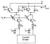
When looking at the on-chip schematics, one notices a Darlington at the output of each active divider (T3 ... T6). These are driven by the active current divider, followed by an RC filter (R1, R2, C1, C2). C1 and C2 are two of the external active divider decoupling caps. R1 and R2 are integrated. This schematic only shows two bits, in The TDA1541A 12 of these circuits are used (2 x 6 MSB for L / R channels).
The remaining 10 bits for L and R are derived using passive current dividers (emitter scaling) so these binary weighted currents aren't dynamically corrected.
The Darlington transistors connect to the output through diodes (D1 and D2). The binary weighted currents can be re-routed by T1 and T2. When T1 for example is switched-off (bit = 1), the current of that divider flows from the output, through the diode, into the current divider. When the transistor conducts, the divider current runs from +5V into the divider, so it won't be added to the total DAC output current.
TDA1541A +5V needs to have very good decoupling in order to prevent ripple voltage due to varying current flowing into the dividers when these are re-routed to the +5V.
Back to the TDA1541A I/V output stage, I figured, what if the external (active) circuit matches on-chip properties, then it would introduce similar THD "finger print" as the on-chip circuit. Thus no other THD spectrum would be added that would further clog-up the spectrum.
So that's what I did, I simply duplicated the TDA1541A internal Darlington and connected emitter to the DAC output (cathodes of internal diodes), basis was connected to 1.2V reference voltage in order to maintain approx. 0V DC at the DAC output.
next I simply connected a 700 Ohm passive I/V resistor between +5V and Darlington output. Works like a charm, 2.8Vpp output signal, clean sound. Problem however is that the connected power amp is referenced to GND while the I/V resistor is referenced at +5V. This means that when power supply impedance is not very close to zero, interference will be added to the output signal.
Here is where the PCB bypass / decoupling cap comes in handy. These forms a very low impedance, much lower than a black gate, ceramic or foil cap. In fact the effect on sound quality was clearly audible. These PCB bypass caps turn out to be superb for power supply decoupling as well.
Other irritating problem with the TDA1541A is the DEM clock that drives the DEM logic and determines bit errors. When this circuit doesn't work perfectly, bit errors / DLE errors will occur immediately. The DEM oscillator frequency also inter-modulates with I2S signals BCK, DATA and WS (on-chip crosstalk). This is not desirable and leads to smeared sound.
Well I have come up with a very simple and effective circuit. One resistor (exactly 13K) connected between TDA1541A pin 16 (pin 17 is not connected) and the existing DJA circuit, thus injecting 1.4112 MHz DEM clock that has same extreme low jitter as BCK timing signal. At this very high DEM clock rate, the 100nF decoupling caps become more effective (same cap and internal resistor value, higher frequency).
I also figured out a way to create high performance decoupling caps for the active dividers. Simply add a small piece of flexible 0.05mm thick PCB material as bypass (approx. 1 x 1 cm piece). The RF / HF interference drops to lowest levels I measured so far. These pieces of flexible PCB material (that are bit thicker than 0.05mm) can be placed between the small 100nF caps.
Hi John ( ecdesigns?) , what do you think of pedja discrete output of tda1541, did you ever tried it ? Its only using one tda and it looks neat
The fact it looks neat is irrelevant, question is how it will perform. I tried it, sound nice, but .....
In order to achieve maximum performance one has to know exactly how the TDA1541A on-chip output circuit functions.
I attached TDA1541A on-chip output circuit. The diodes that are part of the bit switches that determine output compliance. The AC signal has to stay below 0.6V in order to prevent clipping of the output signal (ac voltage exceeds on-chip diode forward voltage).
I tried many external (I/V) circuits, and the best is still passive I/V conversion, no OP-amps no fancy diamond stages, just a plain resistor.
problem with TDA1541A however is that output compliance requires use of active circuits.
When looking at the on-chip schematics, one notices a Darlington at the output of each active divider (T3 ... T6). These are driven by the active current divider, followed by an RC filter (R1, R2, C1, C2). C1 and C2 are two of the external active divider decoupling caps. R1 and R2 are integrated. This schematic only shows two bits, in The TDA1541A 12 of these circuits are used (2 x 6 MSB for L / R channels).
The remaining 10 bits for L and R are derived using passive current dividers (emitter scaling) so these binary weighted currents aren't dynamically corrected.
The Darlington transistors connect to the output through diodes (D1 and D2). The binary weighted currents can be re-routed by T1 and T2. When T1 for example is switched-off (bit = 1), the current of that divider flows from the output, through the diode, into the current divider. When the transistor conducts, the divider current runs from +5V into the divider, so it won't be added to the total DAC output current.
TDA1541A +5V needs to have very good decoupling in order to prevent ripple voltage due to varying current flowing into the dividers when these are re-routed to the +5V.
Back to the TDA1541A I/V output stage, I figured, what if the external (active) circuit matches on-chip properties, then it would introduce similar THD "finger print" as the on-chip circuit. Thus no other THD spectrum would be added that would further clog-up the spectrum.
So that's what I did, I simply duplicated the TDA1541A internal Darlington and connected emitter to the DAC output (cathodes of internal diodes), basis was connected to 1.2V reference voltage in order to maintain approx. 0V DC at the DAC output.
next I simply connected a 700 Ohm passive I/V resistor between +5V and Darlington output. Works like a charm, 2.8Vpp output signal, clean sound. Problem however is that the connected power amp is referenced to GND while the I/V resistor is referenced at +5V. This means that when power supply impedance is not very close to zero, interference will be added to the output signal.
Here is where the PCB bypass / decoupling cap comes in handy. These forms a very low impedance, much lower than a black gate, ceramic or foil cap. In fact the effect on sound quality was clearly audible. These PCB bypass caps turn out to be superb for power supply decoupling as well.
Other irritating problem with the TDA1541A is the DEM clock that drives the DEM logic and determines bit errors. When this circuit doesn't work perfectly, bit errors / DLE errors will occur immediately. The DEM oscillator frequency also inter-modulates with I2S signals BCK, DATA and WS (on-chip crosstalk). This is not desirable and leads to smeared sound.
Well I have come up with a very simple and effective circuit. One resistor (exactly 13K) connected between TDA1541A pin 16 (pin 17 is not connected) and the existing DJA circuit, thus injecting 1.4112 MHz DEM clock that has same extreme low jitter as BCK timing signal. At this very high DEM clock rate, the 100nF decoupling caps become more effective (same cap and internal resistor value, higher frequency).
I also figured out a way to create high performance decoupling caps for the active dividers. Simply add a small piece of flexible 0.05mm thick PCB material as bypass (approx. 1 x 1 cm piece). The RF / HF interference drops to lowest levels I measured so far. These pieces of flexible PCB material (that are bit thicker than 0.05mm) can be placed between the small 100nF caps.
Attachments
Analog Metric PCB's
The analog metric BCB is of very good quality and you can have it as platform for different modifications and testings. Thick glassfiber PCB and the plated holes trough and solder pads are large. You can unsolder and change several times without fearing the solder pads would dissapear. I recommend to not solder trough the holes if it's a component you maybe will change soon. Because it's a PITA to unsolder those, about 4 mm deep holes with a normal handdriven "solder-sucker". With a proffesional station It's another story (easy) The layout is also good. You need some more decoupling caps near the PS pins of TDA1541 and SAA7220. Tantals or maybe try oshcons. I will try to update my homepage later on with my findings there. Good PS and good decoupling gives you best HiFi value for the bucks. The most important one it is.
If you mean the deem decoupling caps I don't think you have to worry.
You need components to build something and you need space. You can't build a DIY circuit without components or space even if some people seems to want that, so that It's really simple and clean One should also not exaggerate the KISS rule .
The PCB card I bought for a CCDA phono amplifier, which now is testplatform for my CCDA I/V stage is very large. But easy to work with. There is room for real components and It's dead quite when it should be... when there is no music playing. I just have to buy a big enclosure when I have to settle that project.
Hi gabdxHi radioman and ecdesign,
I would like to contribute to build this tda1541 dac, i have almost all the parts except the pcb. I can buy the one from analogmetric if it is good, ( I dont like the fact that the coupling caps are that far from the tda
My idea is to try 2x OS , I have no idea how, also to try Radioman output stage, and try some others ...
The analog metric BCB is of very good quality and you can have it as platform for different modifications and testings. Thick glassfiber PCB and the plated holes trough and solder pads are large. You can unsolder and change several times without fearing the solder pads would dissapear. I recommend to not solder trough the holes if it's a component you maybe will change soon. Because it's a PITA to unsolder those, about 4 mm deep holes with a normal handdriven "solder-sucker". With a proffesional station It's another story (easy) The layout is also good. You need some more decoupling caps near the PS pins of TDA1541 and SAA7220. Tantals or maybe try oshcons. I will try to update my homepage later on with my findings there. Good PS and good decoupling gives you best HiFi value for the bucks. The most important one it is.
If you mean the deem decoupling caps I don't think you have to worry.
You need components to build something and you need space. You can't build a DIY circuit without components or space even if some people seems to want that, so that It's really simple and clean
One should also not exaggerate the KISS rule .The PCB card I bought for a CCDA phono amplifier, which now is testplatform for my CCDA I/V stage is very large. But easy to work with. There is room for real components and It's dead quite when it should be... when there is no music playing. I just have to buy a big enclosure when I have to settle that project.
The inside of TDA1541 and 700 ohmfrom output to +5
Do you really mean you can tap that amount of signal between the output and +5 V?
Then a 700 ohm and a transformer (or two caps, one for signal and one for +5V ?) and your done?
What about the current you inject with the 700 ohm resistor at the output of the TDA?
Man, you really try the opportunitys of the TDA1541A. Turning it backwards and inside out and back again
Do you care to share the inside schematics of TDA1541A? Where have you got that from?
next I simply connected a 700 Ohm passive I/V resistor between +5V and Darlington output. Works like a charm, 2.8Vpp output signal, clean sound. Problem however is that the connected power amp is referenced to GND while the I/V resistor is referenced at +5V. This means that when power supply impedance is not very close to zero, interference will be added to the output signal.
Do you really mean you can tap that amount of signal between the output and +5 V?
Then a 700 ohm and a transformer (or two caps, one for signal and one for +5V ?) and your done?
What about the current you inject with the 700 ohm resistor at the output of the TDA?
Man, you really try the opportunitys of the TDA1541A. Turning it backwards and inside out and back again
Do you care to share the inside schematics of TDA1541A? Where have you got that from?
- Home
- Source & Line
- Digital Line Level
- Building the ultimate NOS DAC using TDA1541A