Hello,
I'm working on a digital audio mixer for pro live mixing. I've been researching this for years but recently stumbled on the Teensy 3.6. It has a very nice library for creating an audio flow using a GUI and Arduino code. Check out the Teensy Audio Library here.
My first test was using the Audio Shield and it succeeded at proving that it is capable of doing what I needed, but the quality was pretty bad. So I purchased some cheap modules off ebay. They are a PCM5102A and a PCM1808. I successfully connected them to the Teensy. They worked great and the sound was much better.
Next, I plan on integrating some even better IC's for my project but before I do I was thinking about creating some type of audio bridge for the Teensy. This would make it easier for me to modularize my project and focus on the individual components rather than a full blown board. The plan is to hopefully get some community support. I've outlined the concept on my post about my project on the teensy forum. Check it out and let me know your thoughts. I'm seeking just an overall concept confirmation and maybe some advice on what features should and shouldn't be included on it.
Here is the link to my project and some more information about this potential bridge.
Teensy with PCM5102a Module via I2S
Great project! I am also researching about digital audio mixer recently and I also came across to this teensy. The only problem is that I can only see pin i2s0_rxd0 and i2s0_rxd1 on its datasheet. This means that it only has 2 I2S channels which means you are only limited to 4 channels. Though I haven't dig deeper into this yet.
Have you succeeded in connecting 4 ADCs in this project? I am excited for this one.
For now I am looking into ADAU1701 for my project. But if you succeed in connecting 4 ADCs to teensy 3.6, I might consider this for my project.
Digital Audio Mixer Project with ADAU1701 – tataylino.com
Have you succeeded in connecting 4 ADCs in this project? I am excited for this one.
For now I am looking into ADAU1701 for my project. But if you succeed in connecting 4 ADCs to teensy 3.6, I might consider this for my project.
Digital Audio Mixer Project with ADAU1701 – tataylino.com
Hello tataylino,
I actually reached out to you on your site once when I came across your project. We are going down the exact same path.
I haven't succeeded at connecting 4 ADCs yet, but I know it's possible and proven because the Teensy Audio Shield has it working with 2 shields and a Teensy.
I'm currently contracting Freelancers to begin development of my audio modules. These modules could technically be connected to whatever MCU I decide works. I just want a working mixer. I really don't care which MCU. 🙂
Maybe we can collaborate on this.
Jay
Hello, Good to meet you again! I was a bit busy and haven't have time to start this project yet. But I really wanted this project done. As of now I am spending little time doing research on this project. I quit on the idea of using XMOS because of its availability here and the development board is too expensive. Based on my research, most known digital mixers uses sharc dsp from analog. This is the best solution but the development board is too expensive and there very few resources on the internet about tutorials. I haven't used one on any of my projects. The cheapest and easiest solution I know for now is the ADAU1701.
I have no doubt you can connect 2 ADCs on teensy and I hope you can connect 4 because that would be perfect for this project because the software library are already there and is easy to use. But I can only see 2 I2S on its datasheet.
I found some STM32 MCU that has up to 5 i2s channels which would be perfect. That would mean up to 10 inputs and outputs. But the only problem is that it only runs at 100MHz so I am not sure if that's enough. The presonus 16.4.2 mixer uses a sharc DSP that runs at around 400MHz. But maybe it is ok for basic mixer function with some EQ function.
Maybe we can collaborate on this project. 🙂
Edit:
Yeah, I was right on the I2S channels, teensy 3.6 only have 2 I2S channels.
Why Teensy 3.5 or 3.6
Last edited:
Remember 2 x I2S lines should be 8 inputs and 8 outputs using TDM right? If we had 4 I2S lines we could have 16x16, right? (EDIT: I don't know)
XMOS = Too expensive. Nobody wants to code for it. But it is surely a rock solid platform and I'd love to have a bridge for it. No GUI..... :-/ Here is a link to the forum post I made about this on XMOS forum.
ADAU = SigmaStudio is good. We need a "I2C/I2S Bridge" for it to make it easier. Why didn't FreeDSP just make a bridge. The PiZero seems to be on hold/pause. Maybe we should make a FreeDSP bridge with no codecs or adc/dac. Just I2C/I2S ports...
Teensy = Working for me so far. Going to create two modules (ADC/DAC) and see how many we can connect and make work. They have a TDM example with 16 channels on each i2S channel. Yes I think the software is coded for two I2S channels. However, I counted more when I looked at the pins....
STM32 = AudioWeaver Free Edition is limited but it is a GUI. Maybe if we made a bridge we could "group buy" a license for the Standard Edition and get all functionality. Great Development modules such as Nucleo-F767ZI... I think this one could work too.
Any others I forgot? I'm pretty sure most "PRO" mixers are using XMOS+Sharc. Currently I'll be going down the path of Teensy, but I'm wide open to suggestions.
I attached a pin assignment that I'm working on. There are a bunch of TX/RX lines - am I missing something?
And TDM in the Audio Development Tool is also attached.
Attachments


Last edited:
PS - Danville Signal solutions (XMOS + SHARC)
dspblok 21489uac2 USB Audio Class 2 DSP Module | dspblok | Products
dspblok 21489uac2 USB Audio Class 2 DSP Module | dspblok | Products
1 I2s channel can hold 2 inputs and 2 outputs. So if you have 2 I2S channels then that would be a total of 4 inputs and 4 outputs.
TDM is different. Great find! maybe that's a better option!
TDM is different. Great find! maybe that's a better option!
Yes the TDM is exemplified on this board:
OSH Park ~
And I believe it was based on this project on the forum.
Quad channel output on Teensy 3.6 - Page 2
OSH Park ~
And I believe it was based on this project on the forum.
Quad channel output on Teensy 3.6 - Page 2
It looks like you have done tons of research more than I did. That's great! I think the best option now is that board. Unfortunately I can't see any TDM codec IC that have more than 6 input channels. If teensy could handle 2 CS42448 simultaneously, that would be awesome! that would mean 12 inputs and 16 outputs.
I don't want to use the CS42448. I'm looking at other modules. Maybe I'll post some more information as I move along.
Are you interested in this project personally or commercially? I admit, I have a small commercial interest in mind selling some boards maybe.
Are you interested in this project personally or commercially? I admit, I have a small commercial interest in mind selling some boards maybe.
As of now I only want it to use for our small church. But I also have plans selling it it small quantities. It might take longer because I want a complete product, not just a board. Not to mention a big amount of money involve for manufacturing the enclosure.
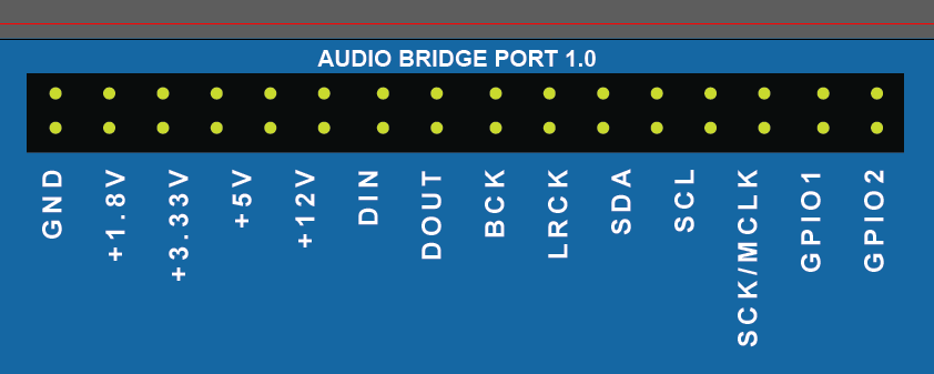
So what do you think about this audio port design? Both the modules and the bridges will have the same ports, so that they can be connected easily board-to-board.
- The footprint will be a 2.54" header that can be right angled for a board to board connection or connected with headers/pins/wire.
- The bridge will contain the Power Regulators so that all the audio ports on the bridge will have whatever power requirement it needs. 12v, 5v, 3.3v, 1.8v.
- I'm trying to decide if the modules should be daisy chainable, so that they can be used in multiples for the TDM lines, or if the bridge module should just have multiple ports for adding more than one module to a line. (I think the later)
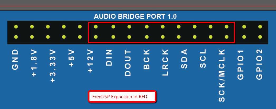
This port would be on both the modules, and the bridges. This header is similar, but a modified version of the FreeDSP expasion connector. They will allow simple connection from board to board with ether edge connectors, or with ribbons. The bridge can be designed for a variety of MCU options. My initial concept is for the Teensy, but the modules, if this port is designed fairly well, can work on any module. So I value feedback so that maybe we can get it right the first time!
- The footprint will be a 2.54" header that can be right angled for a board to board connection or connected with headers/pins/wire.
- The bridge will contain the Power Regulators so that all the audio ports on the bridge will have whatever power requirement it needs. 12v, 5v, 3.3v, 1.8v.
- I'm trying to decide if the modules should be daisy chainable, so that they can be used in multiples for the TDM lines, or if the bridge module should just have multiple ports for adding more than one module to a line. (I think the later)
This port would be on both the modules, and the bridges. This header is similar, but a modified version of the FreeDSP expasion connector. They will allow simple connection from board to board with ether edge connectors, or with ribbons. The bridge can be designed for a variety of MCU options. My initial concept is for the Teensy, but the modules, if this port is designed fairly well, can work on any module. So I value feedback so that maybe we can get it right the first time!
Attachments

Last edited:
I could use some help with my "Audio Port Bridge". Any advice would be greatly appreciated!
The FreeDSP Expansion Connector has a FULL ROW of GND connectors on one side, and the data/power pins on the other. Is this completely necessary? I know that if there isn't a good ground between the boards this can lead to impedance issues. Well, in modern IC chips how much ground is enough? Is this pinout extreme or necessary? Here is a mock design of the pins.
My only fear is that the TE Connectivity Header Pins are super expensive. TE Part # 1-103168-4. We might want to do Edge to Edge connectors instead and set the bridge up in a form factor that works for the modules. Any thoughts?
By the way - what size IDE Ribbon cables and header pinouts are "standard"? While I know there is no standard besides disk drives (IDE Hard Drive Cables are 40 pin) is there any number that is more common than others? 2x13, 2x16, 2x10? I can remove the GPIO pins from my design I think. I have a 12v supply to keep standard with the FreeDSP connector but I wanted to supply the 1.8, 3.3, and 5v lines because I don't want the regulators on every board.
Attachments


Last edited:
As of now I only want it to use for our small church. But I also have plans selling it it small quantities. It might take longer because I want a complete product, not just a board. Not to mention a big amount of money involve for manufacturing the enclosure.
I'm designing modules for ADC and DAC. I'm starting with single chip modules (2in/4in/2out), but then I plan on experimenting with multi-chip modules (8in/8out) which would take advantage of the audio bridge concept by maximizing the inputs and outputs on each "audio bridge port". So I'm trying to create a situation that would allow it to expand into a fairly large mixer. (I think 32x32 is possible, maybe the Teensy can't handle it)
If the Teensy struggles then I can redesign the audio bridge for another DSP combo (maybe STM? Maybe ADAU?)... It would be fairly versatile like that because the modules won't change.
That being said, I do not have any plans for faders, knobs, or sliders. The plan is to control it via MIDI. All of the parameters of the mixer as defined in the DSP will be controlled by an external controller. In my case, a PC touch screen. But if you want a bunch of knobs - you can have a bunch of knobs. You would create a midi controller essentially. This is my strategy to avoid having to pay lots of money to manufacture cases.
I plan on making the Audio Bridge OPEN and the modules commercial. Maybe this can help people to contribute towards the project, and may help with group buying capacities.
Last edited:
Hello,
Its been a while, i was too busy on my work. I have a doubt that teensy could handle 8ins and outs but Im not sure about this. Have you seen the new Arduino MKR Vidor 400? I guess it is a better solution.
Arduino MKR Vidor 4000
I am not sure about the connectors full of ground. I think it is not necessary. I have seen some designs that only have 1 to 3 gnd pins only.
Here is a 2x10 design concept. I guess I will just settle on something at some point! I could even fit what I want in it over 2x8 and still get a bunch of ground pins. I don't know if any parts are easier to get than others.
Attachments

A ground for each signal pin allows you to make impedance controlled transmission line connections between devices. Use ribbon cable with every other conductor a ground. All the ground conductors at each end of the cable should connect to the end device PCB ground plane.
A ground for each signal pin allows you to make impedance controlled transmission line connections between devices
Yes that's what I've read. Thank you for your input. It's just that I've seen many connectors have only 1 GND for every 5 or more pins. So I'm actively debating it. I'm also trying to figure out if there are any cost savings for having smaller headers, smaller IDC cables, etc. 2x14 is quite large! 2x10 seems a little more manageable - seems also a little closer to standard.
The bridge can connect to the modules via cable, stacking, or edge to edge. In the case of edge to edge, there is the issue of having to create a male and female versions (with rows 1 and 2 swapped so that the edge connector "inside" is connected to the reflecting "inside"). At this point in time I am leaning towards a stacking concept (seriously makes it look like a bridge too). It is the cheapest in terms of parts (See attached concept drawling), and it also allows for IDC ribbons easily too.
I'm attaching my latest schematic for the Bridge. It has a power supply, and 4 connectors. Two connectors are connected to one RX/TX line (Serial Data of the I2S), and two to the other RX/TX line. This lets you connect one ADC module and one DAC module to the same line. I might change this up a bit too next week because maximum TDM connections with 8 inputs/outputs on a module would require 4 per RX/TX line (2 8xADC and 2 8xDAC). I might only expose one RX/TX line for the initial prototype but 4 ports. This still allows a 16x16 device. But still possible to maybe have the other side available for the other RX/TX lines.
I'm brainstorming here. 🙂
Attachments

- Status
- Not open for further replies.
- Home
- Source & Line
- Digital Line Level
- Teensy Audio Bridge for I2C/I2S lines