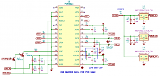
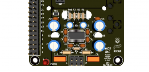
Sounds legit
Good points,
How about ferrites on the PSU's? Input and/or output sides?
I am using LDO, whereas I see ferrites on buck type.
Would a ferrite bead between the isolated ANalog and system DIGital grounds of the DAC still pose a potential issue you figure? Not allowing stray noise on the ANalog ground back to source?
S
The thing to remember about ferrites (Well, lossy inductors generally really) is that current flows in loops (always), adding impedance between two loops is not always a bad thing, but you are usually building a PI network in effect.
Simulations are helpful, but make sure you capture enough of the parasitics, it is very easy to accidentally simulate something with inductors having zero ESR and parallel C and caps having zero ESL and ESR, this tends to look very different to reality.
Remember also that a bead is a lossy inductor, be careful about resonant funnies.
Personally I tend to place an 0603 or such pad and them measure with the zero ohm option and with the ferrite, a spectrum analyser with a DC blocked 50 ohm input is good for this.
If your LDO of choice has poor PSRR at whatever frequency matters (Many of them have very poor PSRR up where switch mode power supplies tend to radiate) then an LC filter in front can help, otherwise why bother?
Beads are a cure for a problem, only apply the cure if you have the problem.
Regards, Dan.
Thanks for the tips
On a prototype, I get static unless I physically touch the board ground, or connect it to the wall ground. In the end, it will be Earth connected, however I would like to see if I can get rid of that beforehand.
A ferrite between the AN and DIG grounds still not a good idea then? I suppose that static could be coming through that AN ground anyway, negating such use.
Thx
Forget the ferrite, especially bw. AGND and DGND!
Connect the board GND to the wall ground with a parallel R-C, and NOT direct (to avoid ground loops between different devices)!
Could we see your project, perhaps would help to recognize the problems...!?
Connect the board GND to the wall ground with a parallel R-C, and NOT direct (to avoid ground loops between different devices)!
Could we see your project, perhaps would help to recognize the problems...!?
BTW
It is quite possible that the noise is coming from my test amp and speaker and it's ground loop.
I am playing around with the prototype to get it to work with an amp that I am building also, so the temp amp and speaker is a toss away item.
The driver for this DAC comes able to configure a switch to start an amplifier, and at the same time, I am making a power switch that actually works like one should, in conjunction with an Adafruit UPS so no data loss or corruption. When all is sorted and tested and most complete, ya'll can have the files, it's actually quite simple. The original worked great with kodi or whatever, although this is ver2
cheers
I have so one, it works well... not the best sound ever heard, but for that (7€) price a bargain...
"It is quite possible that the noise is coming from my test amp and speaker and it's ground loop." Yes, it is possible!
But if you want to make a better DAC, take two separated transformers and PSU for digital and analog side (and design a good pcb layout of course)...
For a first project a good start, but I would consider for example the AK4452(-8) (costs ca. 5€) or better chips.
Attachments
Last edited:
- Status
- Not open for further replies.
- Home
- Source & Line
- Digital Line Level
- General DAC design rules, layout techniques, etc.


