Without a 4 layer design your supply is always compromised. Having a Ground/power plane pair gives the best power supply integrity and best overall signal integrity and the best EMC performance.
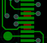
For your digital decoupling use the smallest package X7R you can solder next to the pin, 0402 is best, larger packages are pretty useless to much inductance. if you look at the impedance graphs in the data sheet once they pass the peak the caps are effectively inductors and no use, so small is best. The caps act as a fast current supply when the device switches (power plane capacitance is even better, hence 4 layer boards plus they are low impedance). For the device package used I would use a 4 layer design, place the small local decouplers on the opposite side under the respective power pins, shown below, this gives us in order of importance, on die capacitance, plane capacitance, local decoupler's, reservoir caps, power supply for supplying the switching current. For a 2 layer design... I would place on the same layer as close as possible to the pins, like what you have done on your board.
The best option these days for oscilator's is a local power island supplied by a low noise LDO, in fact because of the size of some of them, they are becoming popular in general for local supplies.
A good pdf showing return paths etc.
http://www.x2y.com/filters/TechDay0...log_Designs_Demand_GoodPCBLayouts _JohnWu.pdf
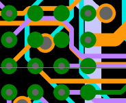
The other picture is HDI layout, via in pad, 2mm per side 0,5mm BGA, 8 layer board copper turned off for clarity.
For your digital decoupling use the smallest package X7R you can solder next to the pin, 0402 is best, larger packages are pretty useless to much inductance. if you look at the impedance graphs in the data sheet once they pass the peak the caps are effectively inductors and no use, so small is best. The caps act as a fast current supply when the device switches (power plane capacitance is even better, hence 4 layer boards plus they are low impedance). For the device package used I would use a 4 layer design, place the small local decouplers on the opposite side under the respective power pins, shown below, this gives us in order of importance, on die capacitance, plane capacitance, local decoupler's, reservoir caps, power supply for supplying the switching current. For a 2 layer design... I would place on the same layer as close as possible to the pins, like what you have done on your board.
The best option these days for oscilator's is a local power island supplied by a low noise LDO, in fact because of the size of some of them, they are becoming popular in general for local supplies.
A good pdf showing return paths etc.
http://www.x2y.com/filters/TechDay0...log_Designs_Demand_GoodPCBLayouts _JohnWu.pdf
The other picture is HDI layout, via in pad, 2mm per side 0,5mm BGA, 8 layer board copper turned off for clarity.
Attachments
How hot will the shunt reg get... Some copper on the board will help protect the board and get rid of a bit of heat if its laid flat.
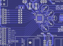
I would move the SCK uhf connector to the end of the line a t junction on a clock line is not a good idea.
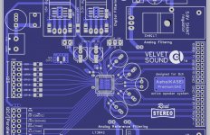
Spread the tracks out a bit more on the left hand side of the AK445, especially the 45 degree ones, minimise crosstalk, coupling etc. Use the board space.
SOIC regulators add more copper if possible and more thermal vias, specify 0.025mm or greater plating thickness.
If you start with 0.035mm (1oz) copper after plating you will have 0.052mm copper, starting with 0.018 (1/2oz) may be a better option for the smaller device.
I would move the SCK uhf connector to the end of the line a t junction on a clock line is not a good idea.
Spread the tracks out a bit more on the left hand side of the AK445, especially the 45 degree ones, minimise crosstalk, coupling etc. Use the board space.
SOIC regulators add more copper if possible and more thermal vias, specify 0.025mm or greater plating thickness.
If you start with 0.035mm (1oz) copper after plating you will have 0.052mm copper, starting with 0.018 (1/2oz) may be a better option for the smaller device.
10uf is pretty small, which is good as the esr won't be as low as a larger size, might work even with a ceramic part nearby. A scope would be the way to check that, although I never have, has been obvious when I heard it.
A small resistor between the oscon and the ceramic part can help to break up a resonance too, but I just place the oscon as close as possible and go without the ceramic part.
A small resistor between the oscon and the ceramic part can help to break up a resonance too, but I just place the oscon as close as possible and go without the ceramic part.
For your digital decoupling use the smallest package X7R you can solder next to the pin, 0402 is best, larger packages are pretty useless to much inductance. if you look at the impedance graphs in the data sheet once they pass the peak the caps are effectively inductors and no use, so small is best.
I definitely agree with you that smaller physical size is better for decoupling, but I don't think capacitors become useless above their self-resonant frequency. No matter whether they are capacitive, inductive or resistive, as long as their impedance is much smaller than the impedance of the supply lines and as long as they don't cause any nasty resonances, they still help to keep the supply impedance down.
I definitely agree with you that smaller physical size is better for decoupling, but I don't think capacitors become useless above their self-resonant frequency. No matter whether they are capacitive, inductive or resistive, as long as their impedance is much smaller than the impedance of the supply lines and as long as they don't cause any nasty resonances, they still help to keep the supply impedance down.
The impedance of the power delivery system varies with the frequency of the operating electronics, so they reduce the impedance at frequencies below their self resonance point, after that they increase the supply impedance.
As a rough guide you need to cater for the main system clock (when most things will switch) and up to the 10th harmonic.
Page 60 shows time domain effect of inductance on the effective power delivery from a cap and the resulatnt noise voltages etc. Heavy stuff but good.
http://web.mst.edu/~jfan/slides/Archambeault1.pdf
yes thats better, the further apart the traces are the less crosstalk you get between lines and thus the best signal integrity and EMC performance.
Signal integrity. EMC are two sides of the same coin. Signal integrity is local EMC issues, crosstalk, impedance mismatches, coupling either capacitively or inductivly to other traces; EMC is the wider effect of whats going on, noise that gets further than the PCB.
Signal integrity. EMC are two sides of the same coin. Signal integrity is local EMC issues, crosstalk, impedance mismatches, coupling either capacitively or inductivly to other traces; EMC is the wider effect of whats going on, noise that gets further than the PCB.
The impedance of the power delivery system varies with the frequency of the operating electronics, so they reduce the impedance at frequencies below their self resonance point, after that they increase the supply impedance.
As a rough guide you need to cater for the main system clock (when most things will switch) and up to the 10th harmonic.
Page 60 shows time domain effect of inductance on the effective power delivery from a cap and the resulatnt noise voltages etc. Heavy stuff but good.
http://web.mst.edu/~jfan/slides/Archambeault1.pdf
Slides 98 to 100 of your reference illustrate the point I'm trying to make. You see that for a given parasitic inductance, the actual capacitance makes hardly any difference as long as it's large enough. Some people desperately try to keep the self-resonant frequency high, which for a given inductance implies using small-valued capacitors, but that's in general completely unnecessary.
Slides 98 to 100 of your reference illustrate the point I'm trying to make. You see that for a given parasitic inductance, the actual capacitance makes hardly any difference as long as it's large enough. Some people desperately try to keep the self-resonant frequency high, which for a given inductance implies using small-valued capacitors, but that's in general completely unnecessary.
Back later...
... but that's in general completely unnecessary.
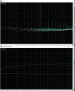
i have tested this on pcm2706 a/d supply pins and there is some difference.
tested is 10uf and 47uf caps or: #10uf-blue #47uf-green on graph on picture.
imd is pretty interesting but i am not sure how good were my tests and is this any representative.
Attachments
Slides 98 to 100 of your reference illustrate the point I'm trying to make. You see that for a given parasitic inductance, the actual capacitance makes hardly any difference as long as it's large enough. Some people desperately try to keep the self-resonant frequency high, which for a given inductance implies using small-valued capacitors, but that's in general completely unnecessary.
True, the difference bewtween 1uf and 0.01uf is minimal. It is the smaller package rather than ultimate capacitance that is important, inductance is the dominant gremlin here.
Gonna dig out and read some more of Mr Archambeault's stuff on this, as well as a few other sources. Often though it comes down to what room you have on a particular design and how much they want to spend on said PCB... HDI (micro-via) gives you the best options, but not many go for it yest, prefer old fashioned drilled holes...
i have tested this on pcm2706 a/d supply pins and there is some difference.
tested is 10uf and 47uf caps or: #10uf-blue #47uf-green on graph on picture.
imd is pretty interesting but i am not sure how good were my tests and is this any representative.
How about the pink traces, what case are they?
I'm sure it's been talked about, but how about the function of ferrite beads? I'm looking to use some in my DAC and know that they are used in grounds etc between the DAC and the sources like USB. What's the take on that? Always a good idea to separate grounds with a bead? Keep the DAC ground isolated? I know they're good on power sources before filter caps. Where else are they used?
Danka
Danka
Hi, I'm not a professional in this theme, but one thing can I say:
you must be careful with ferrites, especially at high frequencies (e.g. I2S lines). These HF signals must flow return to the source (in the ground line). If you split this with a ferrite you will have a big impedance value -> and bad signal integrity...
The best solution is to avoid ground loops with separate PSU for each stage and NOT with ferrites! (but this is my opinion)
If you have a noisy PSU you can try to use them, but please be careful that you do not cause resonances and/or uneccessary dampings!
- Status
- This old topic is closed. If you want to reopen this topic, contact a moderator using the "Report Post" button.
- Home
- Source & Line
- Digital Line Level
- General DAC design rules, layout techniques, etc.