Maybe Sparkos would be a good choice for the differential summing stage. They don't have as much open loop bandwidth as I would like to see for the I/V stages, but the existing opamps are fine there being offset as they are. There has already been some HF filtering before the summing stage, so that would probably be my choice for where to try Sparkos.
If you look at the I/V stage ESS designed into the ES9038PRO evaluation board, it is for about a 3v peak to peak swing. Why? Because if you look at distortion at the differential summing output with a variety of test signals and including for IMD, the distortion is lower that way. If you need really low noise too, you use all 8 output channels in parallel which reduces noise by 3dB with each doubling. Most likely, I would expect when TP releases it's 8-channel output stage for 9038PRO that will be an option.
And, no, I am not taking apart DAC-3 to suit you. Anyway, it has a mulitlayer board and tracing out circuitry in that case can be very difficult.
Maybe consider this: Why are decaying cymbal sounds so revealing of the sound of electronics? Because they are mostly very low level, almost entirely down where distortion is in fact audible.
Also, running that low a voltage will *not* degrade what I want to do. Music is at a low level during parts of every cycle, and during quiet passages. What I want is class A if I can get it.
If you have the eval board for the 9038PRO then you will have the schematic. What Rf is shown for the feedback value that ESS has chosen for the transimpedance stage?
I don't have the board. Feedback resistors are 562 ohm, so maybe they are using more swing. Still not convinced that is path to lowest distortion. There is a problem shown in the distortion graphs that just can't apply to music. Remember, the opamps may be used for oscillators and test tone buffers and things where only low distortion for a fixed high level signal is important. Music is none of those applications, so the graphs should not be misused to conclude things that are incorrect. If ESS is using excess swing, it only shows they are using fixed test tones too. Doh!
There is also a low-cost AK4137 board without SPDIF and TOSLINK inputs. If upsampling and conversion to DSD for USB input only is okay, then one of those could be used.
AK4137 I2S/DSD Sample Rate Conversion Board Supports PCM/DSD Interconversion DOP | eBay
Maybe better to use an Amanero board or a newer XMOS board with two rows of pins because those include some extra signals to automatically indicate incoming digital audio frequency, and DSD or PCM mode. Otherwise, input format for AK4137 might require manual setting.
Also, chances for lowest jitter and excellent conversion might be best with hardware AK4137. Some software conversion might be better, but AK4137 distortion is still rated at -140dB to -150dB, and jitter should be minimal with very short cabling to dac I2S input port and stable source clock. Upsampling itself reduces jitter, so AK4137 should have some jitter reduction effect on incoming audio unless perhaps it is already very low. Maybe Amanero and certain software would be fine, but I have not tested that variation to compare. Sound quality is improved by setting DSD DPLL bandwidth to the minimum stable setting in ES9038Q2M control registers. The lowest DPLL setting that works probably indicates the least incoming jitter, so that would probably be the best way to compare Amanero vs AK4137 DSD jitter.
Also, regarding cost, by the time we upgrade clocks, power supplies, output and AVCC circuits, etc., we have already spent more than the original dac costs. If everything else has been done, the best SQ is with upsampled DSD without question. It also helps to use harmonic distortion compensation because even small improvements there are audible (if everything else has already been made very low distortion), perhaps due to the effects on IMD.
Last edited:
Nice to see someone else is willing to say they agree with me about LDO RF regulators: http://www.diyaudio.com/forums/digi...mate-weapon-fight-jitter-470.html#post5539433
for the unmodified board, upsampling 1kHZ test tone from PCM44.1 to DSD256 caused drop in THD roughly from -76dB to -84dB. one may consider to stop the mods here ")
next, soldering 1500uF in parallel to AVCC caps, leads to -88dB.
so far both 2nd and 3rd harmonics are present.
adding I/V similar to Markw4 outlined, brings THD down to -93dB. 3rd harmonic is gone with this. sound is good and match to PreBoxS2 Digital, which measures about -92dB with stock PS.
for further improvement AVCC/clock etc mods will be required.
just adding, the distortion is minimal at digital volume set at -8 to -10dB for the unmodified board
Last edited:
Maybe Sparkos would be a good choice for the differential summing stage. They don't have as much open loop bandwidth as I would like to see for the I/V stages, but the existing opamps are fine there being offset as they are. There has already been some HF filtering before the summing stage, so that would probably be my choice for where to try Sparkos.
It is probably buried somewhere in this thread, but which opamps are you considering for the I/V stage?
Cheers
Whit
If you look at the I/V stage ESS designed into the ES9038PRO evaluation board, it is for about a 3v peak to peak swing. Why? Because if you look at distortion at the differential summing output with a variety of test signals and including for IMD, the distortion is lower that way. If you need really low noise too, you use all 8 output channels in parallel which reduces noise by 3dB with each doubling. Most likely, I would expect when TP releases it's 8-channel output stage for 9038PRO that will be an option.
And, no, I am not taking apart DAC-3 to suit you. Anyway, it has a mulitlayer board and tracing out circuitry in that case can be very difficult.
Maybe consider this: Why are decaying cymbal sounds so revealing of the sound of electronics? Because they are mostly very low level, almost entirely down where distortion is in fact audible.
Also, running that low a voltage will *not* degrade what I want to do. Music is at a low level during parts of every cycle, and during quiet passages. What I want is class A if I can get it.
You said: Maybe consider this: Why are decaying cymbal sounds so revealing of the sound of electronics? Because they are mostly very low level, almost entirely down where distortion is in fact audible.
I think you hit the nail on the head with this observation. This phenomenon varies with different types of music and source material, of course, but to my ears is most apparent with symphonic music. Especially with pronounced dynamics. Often low-level musical sounds decay into the fuzz introduced by the signal chain (and that includes the recording transducers and electronics).
It is a shame there are no good objective ways to measure and quantify this.
Precisely why audiophiles have long preferred class-A amplification, but often the emphasis is on power amps, and not enough on the rest of the chain.
Cheers
Whit
Thank you, sir. Always nice when we can agree on thingsI think you hit the nail on the head with this observation.
Regarding measurements, we probably should be doing harmonic distortion and IMD FFT measurements at multiple frequencies and amplitudes. At least we should do it once in awhile to get some sense of what shows up in the measurements with different types of output stages.
There is another type of distortion in sigma-delta dacs that is described in the following video link about 40-41 minutes in. The speaker is Martin Mallinson of ESS. Interesting talk, I thought. YouTube
Although I am not aware of a standardized test for the above described transient-distortion, it seems like we should be able to experiment around with some repetitive stepped amplitude modulation of sine waves. Something like that is already commonly used to help characterize audio compressors maybe similar to this: Analyzing Effects: Compression Plugins — Pro Audio Files
However, for transient-related dac distortion we would probably want to try using synchronous averaging FFTs, or something akin that to expose any transient-related distortion artifacts. If we find anything interesting, might be worth trying to make a movie graphically displaying dynamic distortion component levels varying with time.
Last edited:
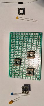
Through-hole, or perhaps better referred to as 'leaded' components arrived today.
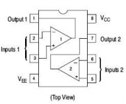
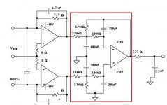
Anyone interested can take a try at a prospective layout. Attached is a pdf of some graph paper that can be printed out. Also included is the pinout diagram of a dual opamp, and a picture of the I/V stage feedback resistor and cap, and also the two bypass caps that go at each power pin. Last picture is the prospective output stage schematic.
In addition, an old post included some info about layout strategy. It can be found here:
http://www.diyaudio.com/forums/digital-line-level/314935-es9038q2m-board-203.html#post5494330
The idea is we want a layout on graph paper showing the bottom view of how we would physically locate components to solder them to dac socket pins. Rules are there will be a ground plane made from copper foil on the bottom of the board covering all perfboard holes that do not have any wiring passing through them. That includes ground plane strips in between the two rows of pins for each opamp socket.
Power wires will be run on the top of the board, and signal wires on the bottom.
Graph paper line intersections will represent holes in the perfboard. Using a pencil, the idea is sketch socket and component dimensions on the graph paper as seen from the bottom side of the board. Power pins need to have one tanalum and on ceramic cap in parallel to ground. They have dimensions as shown together at one side of the component picture.
A hole will be left open in the ground plane next to each power pin to allow power wires to come down from above.
The feedback resistor and capacitor have dimensions as shown on the other side of components picture. The resistor and cap should ideally be mounted on the bottom side of the board and directly soldered to the opamp socket pins. Same for the decoupling caps unless it is preferred to mount them on the top of the board where the power wires come down to the opamp power pins. In that case the ground plane can have an opening for the caps leads to come down and attach to the ground plane.
Feeback resistors could stick straight up in the air from the bottom of the opamp sockets or be arranged laying flat adjacent to the ground plane as is preferred.
Resistors and caps for the differential summing opamp will have similar dimensions. Some filter components may need to be mounted on the top or bottom of the board attached to plated holes without ground plane covering.
The final rule is that there are no rules. All the above verbiage is suggestion only. Contestants should sketch out their proposed component layouts on graph paper using pencil (colored pencil or felt pens, etc. are okay too -- since there are no rules). There is also no contest, but everyone is encouraged to give it try. I won't always be here to do one for you so now would be a good time to try and get some feedback on your layout ideas. Please post a picture of your graph paper with any notes you might want a technician follow. We will give it maybe a couple of days, unless more time is requested, then review the pictures that have been posted. I will post one too at the last second.
It would also be my suggestion to first place the most critical components, then less critical ones and interconnection wiring. The most critical components at the opamp sockets are power decoupling caps and feedback resistor and cap. Keeping leads short length and layout reasonably compact should help maintain good opamp stability.
Everyone who wants to build one of these through-hole components boards should give this layout task a try. It would also be helpful for me to see what you think you would be able to solder together. I might use leaded components to make a very tiny circuit, but someone else might feel that would be almost as hard to assemble as SMD. So, good to show me what you think would be about right for what you consider your assembly and soldering skill level to be.
Please have fun and ask any questions you want. The idea is to learn, have fun, and get comfortable with doing this type of DIY activity.
Attachments
Last edited:
eziitis, Markw4, thank you very much.
I think it would probably be okay with eziitis if I said you are very welcome on behalf of both of us
Also, if I may ask, might you be someone interested in a through-hole component output stage?
Last edited:
While those who are interested in thinking about output stage board layouts mull over how they might arrange electronic furniture in the output stage circuit board space, doesn't mean we can't continue to discuss other things.
With regard to the output stage, I have sort of been thinking about putting some decoupling caps on top of the board, but I just don't want them sticking up too much if really close to the sockets. Reason is because I might want to try some different opamps in the sockets including some that are on adapter boards or that are bigger than typical integrated opamp packages.
In some cases with bigger than usual socketed devices they can need more clearance around the sockets in order to be able to be plugged in. If tall caps are sticking up next to a socket, that can in some cases limit what might be plugged in.
I am thinking that maybe laying the tantalum caps on their sides on top of the board while soldering the smaller ceramic caps directly on the socket pins, down on the bottom could be a good way to go. Probably not necessary or that helpful for the I/V opamp locations, but the differential summing circuit has more components around it, so freeing up any space close to the underside of it's socket might be more helpful.
Another thing to remember about typical dual opamps is they have one end where the outputs are and the other end where the inputs are. Nice to point the sockets with the pin-1 and pin-8 end so that the opamp outputs are closest to wherever the signals need to go next. And similarly, to point the pin-4 and pin-5 end of the socket towards where the input signals will be coming from. In some cases that might not be best, but often it turns out to convenient.
Lot's of little things to think about and consider, maybe not critical things, but some that can help make a less cluttered and more functional layout.
I don't know though. I think maybe to key to some problems like this is just to keep thinking about it at a low level for a few days, then just start placing components tentatively on a drawing and see how it looks. By such means the brain's System 1 can be mobilized to work on a problem in the background, often coming up with a good solution that pops into conscious awareness at some point. In the meantime while System 1 works on the problem in the background, System 2 processes can keep on doing other things in the foreground.
The System 1, System 2 terminology of course comes from the book by Daniel Kahneman, "Thinking Fast and Slow." Excellent book about giving a snapshot of many things discovered about how brains work, at least up to about the time it was published in 2012. Still worth reading, and worth reviewing from time to time. Also closely related but different enough to study separately was Jonathan Haidt's book, "The Righteous Mind," another book worth reviewing from time to time. I mention the books because they are useful to understand about in everyday life, but also because sometimes I will borrow from the terminology when explaining about brains, just as we use certain terminology to talk about electronics.
Hope you all have a great day today!
Last edited:
Markw4, how effective is the investment of money in the AK4137, because it costs as two DAC boards.
Hi KoAP,
Forgot to mention that if you decide to go for the lower cost AK4137 board, I made some pictures showing how to wire it up to the dac, and the Amanero or XMOS board, which is a bit more complicated than for other similar types of devices: http://www.diyaudio.com/forums/digital-line-level/314935-es9038q2m-board-204.html#post5495993
Maybe consider this: Why are decaying cymbal sounds so revealing of the sound of electronics? Because they are mostly very low level, almost entirely down where distortion is in fact audible.
Also, running that low a voltage will *not* degrade what I want to do. Music is at a low level during parts of every cycle, and during quiet passages. What I want is class A if I can get it.
@Mark4. Can you post a characteristic track with just a short part of those cymbals or a similar test audio file you usually use? Flac format would be great.
Think there are a small number of cymbal crashes with adequate space afterwards in this: Dropbox - 16-44kHz.wav
By the way, that should sound gorgeous if the system is good. It was well recorded and mastered for the particular genre of music, IMHO. It is just a snippet from Steely Dan's Aja album. That was perhaps the cleanest of their productions, and something many recording engineers have said they use as a reference if going after a particular kind of sound.
EDIT: Don't know if listening to cymbals with only one dac to listen with would be very useful. It can be good for listening to if comparing dacs, or if you have a high quality physical cymbal to compare with. In other words, it can be easy to feel that a dac playing a cymbal sound is doing a pretty good job when in reality it should sound so much better (more musically detailed and less distorted).
Last edited:
May I ask if anyone else besides me has been thinking abouts the output stage layout problem I posted yesterday?
Been thinking about it myself for about 24 hours (in the background only). It's getting clear enough in the mental picture that I could probably just start building and skip the drawing, and still have it come out in the end without any regrets.
However, I have done this before enough times that I may not need the practice so much someone newer to it. Probably not wise for beginners to take the attitude I described above and just start soldering.
If nobody had laid a pencil to paper at all so far, I hope that at least some mental imagery activity has started. For those that have no time, I guess not much I can do to help out there. For those without motivation, if you want to have a nice dac and improve your electronics construction skills, probably be really good to get started on it in a free moment, and then come back to it as you are able.
And for those with lots of experience who find the whole exercise trivial, please do show off and let us see what you can do. Be a lot of fun hopefully educational for the beginners.
- Home
- Source & Line
- Digital Line Level
- ES9038Q2M Board