I also though it was odd to suggest such a huge part for something that requires such a tiny amount of power instead of another means to a quiet source. [...]
In fact, there is a controversy about that extra cap in the AKM4490 datasheet. The curious fact is that there had been a datasheet update in course, and the new one does not show this part any more!
Do any of You have any more insider insight on it?
AKM is a little more specific in the AK4493 datasheet:
"The differential voltage between VREFHL and VREFLL, and VREFHR and VREFLR set the full-scale of the analog output range. The VREFHL/R pin is normally connected to 5.0V reference voltage, and the VREFLL/R pin is normally connected to the 0V reference voltage. Connect a 0.1µF ceramic capacitor and 470µF (min. value depends upon power supply quality) electrolytic capacitor between VREFHL and VREFLL, and VREFHR and VREFLR. Especially the ceramic capacitors should be connected as near as possible to the pin. The VREFHL, VREFHR, VREFLL and VREFLR pins should avoid noises from other power supplies. Connect the VREFHL/R pin to the analog 5.0V via a 10Ω resistor, and the VREFLL/R pin to the analog ground via a 10Ω resistor when it is difficult to obtain expected analog characteristics because of noises from other power supplies (A low pass filter of fc=17Hz will be composed with the 470µF capacitor and the 10Ω resistor. It removes signal frequency noise from other power supply lines)."
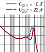
You are right too, I thought the graph expresses itself:
I referred to the bandwidth limitation region of the graph only. If Cout is 22uF, you are right - PSRR increases, but the inflection point of the graph is moving to the left and as you can see, if there is a ripple in the input circuit to aprox. 1.8Mhz is better for Cout to be 10uF because in the 22uF situation PSRR is already descending.
I admit it may look strange to someone who cannot read my thoughts.")
I admit the talk about 'inflection point' and such is creative. ;-) But it is not really about inflection point or bandwidth of PSRR. It is about the absolute value at each frequency, and with larger C the curve is always the same or above than with lower C. So higher C is better for PSRR.
Jan
As I already told you, I was referring to the region where the larger C curve is not above to the lower C curve, in the following context:I admit the talk about 'inflection point' and such is creative. ;-) But it is not really about inflection point or bandwidth of PSRR. It is about the absolute value at each frequency, and with larger C the curve is always the same or above than with lower C. So higher C is better for PSRR.
Jan
- the manufacturer says "larger values of output capacitor only marginally improves the performance because the regulator bandwidth decreases with increasing output capacitance"
- the graph in the datasheet only shows 2 close values 10uF and 22uF, but we were talking about 560uF and the difference between its curve and the lower 10uF C curve should be more significant.
Attachments
Right back at youI missed that part - about audiophiles, it is about the perception, everybody has it's own datasheet. Good luck.
Where did this quote come from ? It seems to match my understanding."For stability, use a minimum 10µF
output capacitor with an ESR below 20mΩ and an ESL
below 2nH. Large load transients require larger output
capacitance to limit peak voltage transients.[...]
Given the high PSRR and low noise performance attained
using a single 10µF ceramic output capacitor, larger values
of output capacitor only marginally improves the perfor-
mance because the regulator bandwidth decreases with
increasing output capacitance — hence, there is little to
be gained by using larger than the minimum 10µF output
capacitor. Nonetheless, larger values of output capacitance
do decrease peak output deviations during a load transient."
Page 13 (OUT (Pin 10/Pins 11, 12)Where did this quote come from ? It seems to match my understanding.
and page 16 (Stability and Output Capacitance) from LT3045 datasheet.Hi
Would the LT3045 /3094 have a problem or a significant drop in performance if there are four 560uF SANYO OS-CONs on the PCB behind it?
https://hr.mouser.com/datasheet/2/315/AAB8000C247-1131709.pdf
Would the LT3045 /3094 have a problem or a significant drop in performance if there are four 560uF SANYO OS-CONs on the PCB behind it?
https://hr.mouser.com/datasheet/2/315/AAB8000C247-1131709.pdf
Hi
Would the LT3045 /3094 have a problem or a significant drop in performance if there are four 560uF SANYO OS-CONs on the PCB behind it?
https://hr.mouser.com/datasheet/2/315/AAB8000C247-1131709.pdf
After the regulator? You effectively decrease the bandwidth with huge caps.
At the input? No problem, but sounds like overkill.
Says he who claims the 78xx series is good enough!!
Why? Anyone can make bland claims but without evidence to back them up they have no validity
I think I'll stick with Linear Technology's list of suggested uses for the LT3045 until I done the auditoning.
A LM317 + two vanilla BJTs (bc337+bc557) best LT3042 for noise, psrr and output impedance in the whole audio band.
Look up lm317 denoiser/nonoiser. Also dienoiser sits somewhere in between denoiser/nonoiser for performance.
edit: there's also a denoiser circuit for 78xx type regs that is called fixnoiser or something like that and it also allows to vary the output of a 7812 for example, if I remember correctly. Also the denoiser works for lm337 negative regulators.
2nd edit: also they make the output cap's quality irrelevant, as in it doesn't need to be some special super low esr or large capacity.
Last edited:
Can you help me with the recommendation of choosing a voltage regulator for analog stage DAC? LT3045 and LT3094 or TPS7A4701 and TPS7A3301 are both perfect. Does anyone have any experience with the mutual comparison of TI and AD, please? I stand before decision which to use, both are available to me, both are excellent, but somewhere I read that TI sound better. I can't decide. Has anyone tried to compare these regulators in any device?
I want to use LT3042 for Vref.
I want to use LT3042 for Vref.
A nice fals urban legend?
A LM317 + two vanilla BJTs (bc337+bc557) best LT3042 for noise, psrr and output impedance in the whole audio band.
Look up lm317 denoiser/nonoiser. Also dienoiser sits somewhere in between denoiser/nonoiser for performance.
edit: there's also a denoiser circuit for 78xx type regs that is called fixnoiser or something like that and it also allows to vary the output of a 7812 for example, if I remember correctly. Also the denoiser works for lm337 negative regulators.
2nd edit: also they make the output cap's quality irrelevant, as in it doesn't need to be some special super low esr or large capacity.
To be more precise, there is no treatment that can transform an LM317 (10kHz bandwith) in something even closely acceptable, for filtering a Dac reference.
(LT3042 /94 is minimum 1MHz bandwith in basic configuration - that is, 2-5 mohm output impedance, to over 1MHz)
A dac reference is the typical load with high frequency load currents up into the MHz region.
Who cares about the performance only in the audio frequency range?!
(LT3042 /94 is minimum 1MHz bandwith in basic configuration - that is, 2-5 mohm output impedance, to over 1MHz)
A dac reference is the typical load with high frequency load currents up into the MHz region.
Who cares about the performance only in the audio frequency range?!
If increasing capacitance results in reduced bandwidth what happens with super capacitors on the output, like with ian canada's ultra cap boards?
The reg rendered effectively useless?
Or the bandwidth is dependant on frequency response of the caps, so for a large super cap bandwidth reduction would be inverse, from DC up?
The reg rendered effectively useless?
Or the bandwidth is dependant on frequency response of the caps, so for a large super cap bandwidth reduction would be inverse, from DC up?
To be more precise, there is no treatment that can transform an LM317 (10kHz bandwith) in something even closely acceptable, for filtering a Dac reference.
(LT3042 /94 is minimum 1MHz bandwith in basic configuration - that is, 2-5 mohm output impedance, to over 1MHz)
A dac reference is the typical load with high frequency load currents up into the MHz region.
Who cares about the performance only in the audio frequency range?!
So, maybe please describe how a bump in the output impedance, say between 3-8MHz, of a regulator, powering a 49 MHz crystal, effects the analog, audible, output?
//
To be more precise, there is no treatment that can transform an LM317 (10kHz bandwith) in something even closely acceptable, for filtering a Dac reference.
(LT3042 /94 is minimum 1MHz bandwith in basic configuration - that is, 2-5 mohm output impedance, to over 1MHz)
A dac reference is the typical load with high frequency load currents up into the MHz region.
You could put a couple of 10 uF X5R SMD capacitors right next to the DAC, with a bigger cheap aluminium electrolytic capacitor in parallel to keep the LM317 stable.
So, maybe please describe how a bump in the output impedance, say between 3-8MHz, of a regulator, powering a 49 MHz crystal, effects the analog, audible, output?
//
It won't as long as it is not bad enough to cause the oscillator to start oscillating at 3 to 8 MHz instead of 49 MHz. It's a different matter altogether for the reference regulator of a sigma-delta DAC, though: there it could cause out-of-band signals between 3 MHz and 8 MHz to mix into the audio band.
it's not called in any way...it was just used extensively by Technics in some high end cd-players of the late 80's ...and it can be easily modified for any higher voltage than 5v by using 78/7905 plus appropriate zenners.edit: there's also a denoiser circuit for 78xx type regs that is called fixnoiser or something like that and it also allows to vary the output of a 7812 for example, if I remember correctly. .
https://www.diyaudio.com/forums/power-supplies/359652-fine-ic-voltage-regulators-28.html#post6353344
Attachments
As I originally said;
"I tried an additional 560mfd Kemet Alu. Polymer output cap on a 1.0A Ldovr module, and removed it due to damage to the sound quality. (this also puts doubt on the Stammheim modules, in my mind, due to large output caps)"
3 or 4 other audiophiles, and myself, have directly experienced a degraded sound quality with larger (560uf in my case) Cout, and someday I might like to try some of Stammheims high current LT3045 modules, but I believe they have even higher Cout's, which gives me pause for their potential SQ contribution (along with their higher prices).
So I'm trying to sort what is going on with LT3045 Cout values, dielectric types, and SQ results. Ok ?
Old post but I just read this > I am one of those that found the same with Stammheim 6 x LT3045 PSU. In fact I got it from a member that was not satisfied with it. I changed the 560 µF caps to 2 x BG N series 4.7 µF in antiparallel config just as these were the only 4.7 µF caps I had. Instant improvement.
Explanation is lacking but now I like this PSU and its performance.
Last edited:
To be more precise, there is no treatment that can transform an LM317 (10kHz bandwith) in something even closely acceptable, for filtering a Dac reference.
(LT3042 /94 is minimum 1MHz bandwith in basic configuration - that is, 2-5 mohm output impedance, to over 1MHz)
A dac reference is the typical load with high frequency load currents up into the MHz region.
Who cares about the performance only in the audio frequency range?!
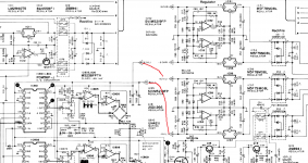
A filter+voltage follower with ne5534 is more than enough for Vref for noise and output impedance. Noise around -170dB and ultra low output impedance. Bonus you have a sense line directly at the Vref pin:

Schematic posted by JohnW here:
Capcitor type for Vref
Total current draw of Vref is around 1mA so should be no issues for ne5534. And it's ultra cheap.
I was thinking about lm317+De/Dienoiser directly for AVCC.
You should show counter measurements if you want to state that the lm317+denoiser doesn't perform as stated. Nonoiser more specifically beats the LT3042 for output impedance, psrr and noise in the audio range. Digital is another matter and I have not recommended it for that.
If you're going to state that lm317+de/die/nonoiser is an urban legend, you really need to show some counter measurements to support your statement. There's been already a few people that measured these circuits and some of them had issues with the noise floor of their measuring equipment to be able to correctly measure the circuits.
it's not called in any way...it was just used extensively by Technics in some high end cd-players of the late 80's ...and it can be easily modified for any higher voltage than 5v by using 78/7905 plus appropriate zenners.
https://www.diyaudio.com/forums/power-supplies/359652-fine-ic-voltage-regulators-28.html#post6353344
I wasn't talking about that. I'm refering to the dienoiser circuit that has been adapted for 78xx regs. It's called Fixnoiser and also provides variable output out of the fixed voltage output regs. They should be performance wise between a denoiser and dienoiser.
This is the schematic for the fixnoiser which has variable output out of a fixed output 7815, from this post D-Noizator: a magic active noise canceller to retrofit & upgrade any 317-based V.Reg.
And this is how this version simulates:
So far I don't think anyone built and measured the 78xx versions yet. The pcb designs I made should be compatible with them tho, maybe someone does make and measure them at some point.
Last edited:
Measurements done in isolated situation... versus real life situation in noisy environment....the smaller the circuit the better....the closer to the IC the better... tiny SMD versus large TH (with free antenna)
As the thread is called "Low noise regulator for DAC & clock" measuring both circuits in real life PCB/situation of a DACs & clock may end the discussion.
As the thread is called "Low noise regulator for DAC & clock" measuring both circuits in real life PCB/situation of a DACs & clock may end the discussion.
Last edited:
- Home
- Source & Line
- Digital Line Level
- Low noise regulator for DAC & clock