OK I will do.
Felipe
Hi Felipe.
I make no claim to electronics expertise so this may be like the blind leading the blind but, looking at the pictures again...
Brown, green and orange wires take the digital signals for DSD-L, DSD-R and Clock from the isolator to the FF board (pins 13, 14 & 15)?
You have three white ground wires from the isolator to FF (pin11)?
You have 5VDC supply to the screw terminal connector on the FF board? you power the isolator board via the black and red wires from the screw connector to the isolator? The isolator says 3.3V supply?
You seem to have a lot of ground connections. Disconnect the white wires from pin11. The Reflektor, Isolator and FF boards will all reference via the ground connection of the screw terminal connector.
If you use the SE board, with everything else the same (except the Ballsie), it all works, just with the lower output level?
Have you tried the FF board connected direct to the Amanero, without the Isolator? Could you make up a really short ribbon connector to connect the Amanero to pins 11, 13, 14, 15?
Ray
No to excuse me about the poor wiring, the same wiring worked OK with Sidecar.
PIN 13 Brown DSD-R
PIN 14 Orange DSD-L
PIN 15 Green CLOCK
Yes all three white wires are GND of DSD-R, DSD-L & CLOCK
Isolator tolerates 5V, worked OK 1 year or more.
If you use the SE board, with everything else the same (except the Ballsie), it all works, just with the lower output level? Yes
Without the isolator add big buzz noise so worse.
Felipe
Attachments
![WP_20160409_001[2].jpg](/community/data/attachments/512/512067-a3df547e374b7ed777238b78e2e125e1.jpg)
![WP_20160409_002[1].jpg](/community/data/attachments/512/512079-c5d0e31677d9c56ab2d1480333f8b3e9.jpg)
![WP_20160409_003[1].jpg](/community/data/attachments/512/512088-f9c82124234e0155079e228081fbd0cf.jpg)
I've just been listening to my modified FlipFlop based project and the results are amazingly good and with no audible noise.
I'm using a JLSounds USB board with the flipflop board piggy-backed onto the headers. The FlipFlop board has LP filters at 40KHz (Rf = 390R, Cf = 10nF). The balanced output goes to a balanced shunt attenuator then to a Broskie BCF Bal to SE buffer. DSD material is upsampled to DSD256 using HQPlayer.
I modified the project by adding in the attenuator; originally I planned to use the HQPlayer digital volume control but that produced a lot of white noise, which disappeared when the HQP volume control was disabled.
Here are a couple of pictures;
I received the extra batch of PCBs this morning so I actually made one of them up and installed it; I just need to enable and set up the mute function now, hence the empty IC sockets.
As said above, I have no white noise. I'm controlling the stop/start bumps with the volume control until I install the mute circuit components.
Ray
I'm using a JLSounds USB board with the flipflop board piggy-backed onto the headers. The FlipFlop board has LP filters at 40KHz (Rf = 390R, Cf = 10nF). The balanced output goes to a balanced shunt attenuator then to a Broskie BCF Bal to SE buffer. DSD material is upsampled to DSD256 using HQPlayer.
I modified the project by adding in the attenuator; originally I planned to use the HQPlayer digital volume control but that produced a lot of white noise, which disappeared when the HQP volume control was disabled.
Here are a couple of pictures;
An externally hosted image should be here but it was not working when we last tested it.
An externally hosted image should be here but it was not working when we last tested it.
I received the extra batch of PCBs this morning so I actually made one of them up and installed it; I just need to enable and set up the mute function now, hence the empty IC sockets.
As said above, I have no white noise. I'm controlling the stop/start bumps with the volume control until I install the mute circuit components.
Ray
As I mentioned in my last post, I have now received the extra batch of PCBs this morning.
I know of two from the original group buy who hadn't received their boards about a week ago so I'll contact them and arrange to send replacements. After that is done I think I'll have about 10 of each sort of PCB available for latecomers.
The extra batch of PCBs are the same as the previous ones except;
- I fixed the error
- I removed the mounting hole tabs.
If the flip-flop is wired to divide by two then you may be corrupting the DSD signal, but perhaps in a way which is not immediately obvious to the ear.
If the flip-flop is merely passing the signal on, then a single logic gate would do instead.
In either case you need a good supply rail for them, as you are listening to the supply rail modulated by the final gate and then low pass filtered (either explicitly or accidentally).
My suggested refinements are a small PCB with a large ground plane, and a 0.1uF cap right between the 74HC74 VCC and Gnd pins. And perhaps an extra R/C filter as I mentioned in the other post.So I'm going backwards in the thread....
Who'd you buy it from? Mouser and Digikey have 'em for less than 50 cents each!!!
Part of this is the "balanced" output has 3dB higher signal, but from your description the transformer was excessively loading the original DSD output, and the 74HC74 outputs have greater drive capability.
I am listening to some recordings my audio buddy made through my Tascam DSD recorder. We have been recording LPs at DSD128, and playing these back right now -- wow, sounding very good.
The whole thing is only prototype and far from optimised. The power is from a computer SMPS, 5 volt output is going directly to flip flop and I am using a 3.3V reg between the 5V and the USB board. And the wiring - well I grew up wiring point to point, which is OK in valve amps maybe but in high speed digital circuitry - I am getting a fair bit of noise. But that's all OK, now I have something that works I can fine tune it because there is heaps of potential.

As far as terminology, the 74HC74 as used is arguably a "dual 1-bit DAC", and indeed a good power supply is critical because the PSRR here is 0 dB. Any variation of the 74HC74 Vcc line directly modulates the output.[/QUOTE]
Actually this is not true. Like most decent quality "modern" dac chips, the CS4398 uses multibit sigma delta modulation. Usually it's around 4-6 bits and several MHz, depending on the chip.
Something like 20 years ago, the 1-bit noise shaped DACs appeared, took over the audio world, and buried the old multibit dinosaurs (PCM63, TDA1541 etc). This happened based solely on price. It is much cheaper to make a 1-bit DAC (it is basically a little CMOS DSP) than a PCM63 or the like (analog process, bicmos, needs very precise matching, thin film resistors, etc). Of course, most of those 1-bits were horrible sounding, but that's not the point. They measured "not too bad" and were cheap. This was a very sad time for hifi.
A bit later, around year 2000 or something, the chip manufacturers developed the current concept of multibit delta sigma, and how to manufacture it cheaply. Not as cheap as 1-bits, but acceptably cheap (ie, not PCM1704). Since those new DACs are better than 1-bits on everything, like measured performance, but especially sound quality, we can finally forget that painful time and move on.
So... you can still find plenty of 1-bits, in lots of application, where it has to be very cheap (like cellphones or other low quality audio) or cheap and linear but slow (industrial), that kind of stuff. And SACD.
Anyway. One of the biggest problems of 1-bits is that it is difficult to make an analog output stage for it, because of the high slew rate and huge amount of HF noise. Opamps fail at this, sometimes spectacularly, depending on the implementation.
This is why everyone upsamples their DSD, filters it in DSP and outputs it using multibit modulator. All DSD-compatible DACs do this, because if you design a chip, that's the only reasonable thing to do.
The other way to do it is to use an analog output stage that doesn't care about HF noise or slew rate, like a transformer. I had tried that on a CD63SE back in the day. It still sucked, but less than the original.
Of course since your DAC is basically a logic gate, and its output is the product of its power supply and the digital value, it means you have to use a balanced output... for example you can use a 74HC flop with normal and inverting output. It should have a very clean power supply... and some filtering on the output... and then your transformer.
Sorry, I jumped to a conclusion: that someone messing with digital electronics and choosing a flip-flop would know enough digital electronics to know what a flip-flop does (and what a logic gate does).
No, a logic gate has one output. However, it is trivial to arrange two suitable logic gates to get complementary outputs.
You will still get noise IM, as it is the supply rail which sets the voltage gain of the output stage. The rail must be very clean, probably cleaner than usually required for normal analogue stages. Normal analogue stages have their gain loosely set by the supply rail; this analogue stage (yes, it is an analogue stage even though it uses 'digital logic') has its gain set directly by the supply rail.
Last edited:
Felipe, your point is?
I think you've taken a hit and are grasping at straws.
I've just posted my own project, which is using exactly the same flipflop board as yours and it works perfectly.
The populated FlipFlop board you're using worked perfectly when I tested it before I sent it to you.
I'm sure the issue is within your implementation.
Ray
Ray, I am not angered, with my system I do not need Flip Flop's gain and can listen without any noise only with the LP filter, also I only have words to say thanks to you and your effort to make the pcbs avaialable for us.
I asked Salas about if the Reflektor-D shunt regulator is the best suit for the FF, because DF96 considered the Flip Flop as an analog stage, let see what says Salas if it's better to use the BiB in place of the Reflektor or not.
I only noted the other people posted about the relation between the PSU an the Flip Flop gain.
As you can see I modified my wiring to 3 cm I2S between the Amanero & the FF and used twisted wires between the FF & the Balsie, also the Balsie connections are confirmed by Brian TP that are OK.
No worries I'm learning step a step, now I will take the scope to se what's happen in PSU rails whe the FF is connected.
Felipe
Well some data:
Reflektor-D supplies 5.4VDC to FF
FF draws 10mA
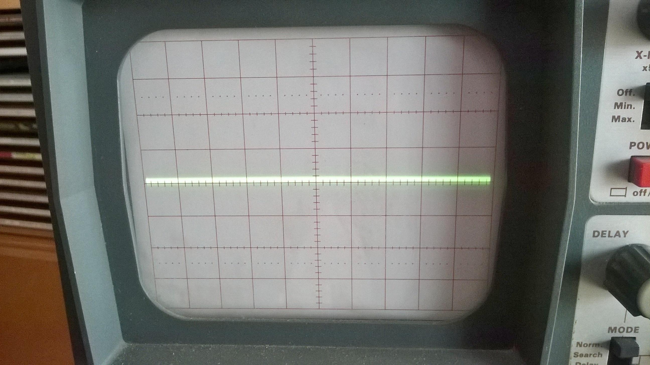
Attached scope pics with FF connected to Reflektor-D and 560R dummy load connected to to Reflektor-D, the scope straight line is the dummy load.
Reflektor-D supplies 5.4VDC to FF
FF draws 10mA
Attached scope pics with FF connected to Reflektor-D and 560R dummy load connected to to Reflektor-D, the scope straight line is the dummy load.
Attachments
![WP_20160409_006[1].jpg](/community/data/attachments/512/512712-d4f7a5b4e06b97b413892e2a81fab8d1.jpg)
![WP_20160409_007[1].jpg](/community/data/attachments/512/512728-cdd05990d9ac3dfd17d6a3255b9ddcb6.jpg)
![WP_20160409_009[1].jpg](/community/data/attachments/512/512737-f0eba273cdace586f96e21f89208bc4f.jpg)
![WP_20160409_010[1].jpg](/community/data/attachments/512/512754-d792b28d2b05cf279a3fdb07e0394df7.jpg)
![WP_20160409_011[1].jpg](/community/data/attachments/512/512775-a51dc3bfcb47c2c864850a2b82ca1ac7.jpg)
![WP_20160409_012[1].jpg](/community/data/attachments/512/512786-2f4b1aa25e39339323cb0fa333dfc92e.jpg)
Ray, I am not angered, with my system I do not need Flip Flop's gain and can listen without any noise only with the LP filter, also I only have words to say thanks to you and your effort to make the pcbs avaialable for us.
I asked Salas about if the Reflektor-D shunt regulator is the best suit for the FF, because DF96 considered the Flip Flop as an analog stage, let see what says Salas if it's better to use the BiB in place of the Reflektor or not.
I only noted the other people posted about the relation between the PSU an the Flip Flop gain.
As you can see I modified my wiring to 3 cm I2S between the Amanero & the FF and used twisted wires between the FF & the Balsie, also the Balsie connections are confirmed by Brian TP that are OK.
No worries I'm learning step a step, now I will take the scope to se what's happen in PSU rails whe the FF is connected.
Felipe
Hi Felipe. Apologies, I was not implying that you are angry, though I imagine you are a bit frustrated. No, my point was that you cannot be far away from success if only we can find the problem that is causing the noise. I think those quotes you listed are an unnecessary distraction and they have been shown to be wrong in that there are a number of successful implementations and I think several of them were posted by people more interested in their own ego than the project anyway.
Regarding the FlipFlop, it is a digital device; it takes a digital input and delivers digital outputs. It could only be a dual 1bit DAC if it's outputs were analogue, which they're clearly not. It also needs a clock signal to drive it, unlike the SE board.
I think the all digital nature might be the root of the problem your seeing with the FF and why there is a difference in the results between the SE and FF boards. With the FF you're running digital signals, including the clock over quite a distance (20cms or so) of sub-optimal wire at the end of which you're expecting to process them as time sensitive digital audio data (that's what the FlipFlop device does). With the SE board you're treating the DSD data as an essentially analogue audio signal. Perhaps that is why my FlipFlop board, which has very short paths for the digital signals, works properly?
Anyone with some expertise care to pitch in on this?
BTW, for what it is worth, I use a pair of these for powering my JLSounds USB and FlipFlop boards;
http://www.diyaudio.com/forums/vend...ow-noise-ldo-regulator-pcb-5.html#post4239877
Ray
Last edited:
Ray as you can see FF produces some modulation on the first scope picture.
Felipe
Ah, I see. I was looking at the 3rd and 6th pictures and couldn't see the FF connected in either?
The 1st picture is the scope connected to FF PSU, you can see the modulation.
The 2nd picture is the scope settings 20mV/cm 20uS when measured the FF PSU
The 3rd picture is connected the 560R dummy load to simulate the 10mA of consumption of FF, 5.4VDC / 560R = 0.01A = 10mA.
The 4th pciture is the scope connected across the dummy load, as you can see there is no modulation: straight line.
The 5th picture is the scope settings 20mV/cm 20uS when measured the dummy load.
The 6th picture is the scope probes connected to dummy load.
Hi Ray,
Felipe clued me in to this project, very excited to try it. I'm ordering the JLSounds board, and just got a SDTrans384. So do you have both the SE and FF boards available still?
Thanks, I'll PM you my shipping address
Adam
Yes, I have both types of board available. I'll PM you the details.
Ray
- Home
- Source & Line
- Digital Line Level
- The Best DAC is no DAC