Hi Ake,
If you want you can send me your nsf file and I'll see if I can reshuffle your filters so that they fit with the 192 kHz sampling frequency.
Best,
Nick
If you want you can send me your nsf file and I'll see if I can reshuffle your filters so that they fit with the 192 kHz sampling frequency.
Best,
Nick
It´s going to be a while until I can try it in my "rig" that´s why I asked.
But I have it connected to my laptop and I tried to create a 192khz filter,but with the 4 equs that I have to use with my PA woofer the core was up to about 110% so I figure that´s to much anyway so thats way I figured I use 96khz..
Hi Ake,
If you want you can send me your nsf file and I'll see if I can reshuffle your filters so that they fit with the 192 kHz sampling frequency.
Best,
Nick
Ok,but I get invalide file when trying to attache the file,do you have an ordinary e-mailadress?
Ok,but I get invalide file when trying to attache the file,do you have an ordinary e-mailadress?
Rename the extension as txt instead of nsf, it should be fine.
(Otherwise yes I have an email address, you got a pair of emails from me, remember?
") )
)So like txt file it should work.
The curves might look kind of strange but I took them directly from nanodigi (minidsp) and they sounds fine.(PA woofer weak low end)
Except for the Q on the 70hz EQ should be 0.8 but it keeps jumping back to 3.00.
Just hope you can take the EQ from nano digi and use it in Nadja,that woofer curve did look strange..
Attachments
Last edited:
Nick, quick question,
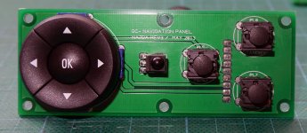
Im using illuminated buttons for the controlpads. Each switch has an LED built in that draws 20ma @3v. In total there are 8 LED's.
Is it possible to power it them off one of the headers on the board?
Thanks.
Same here.
... or is it possible to power the LEDs over the dimmable backlight together with the lcd-panel?
Hi,
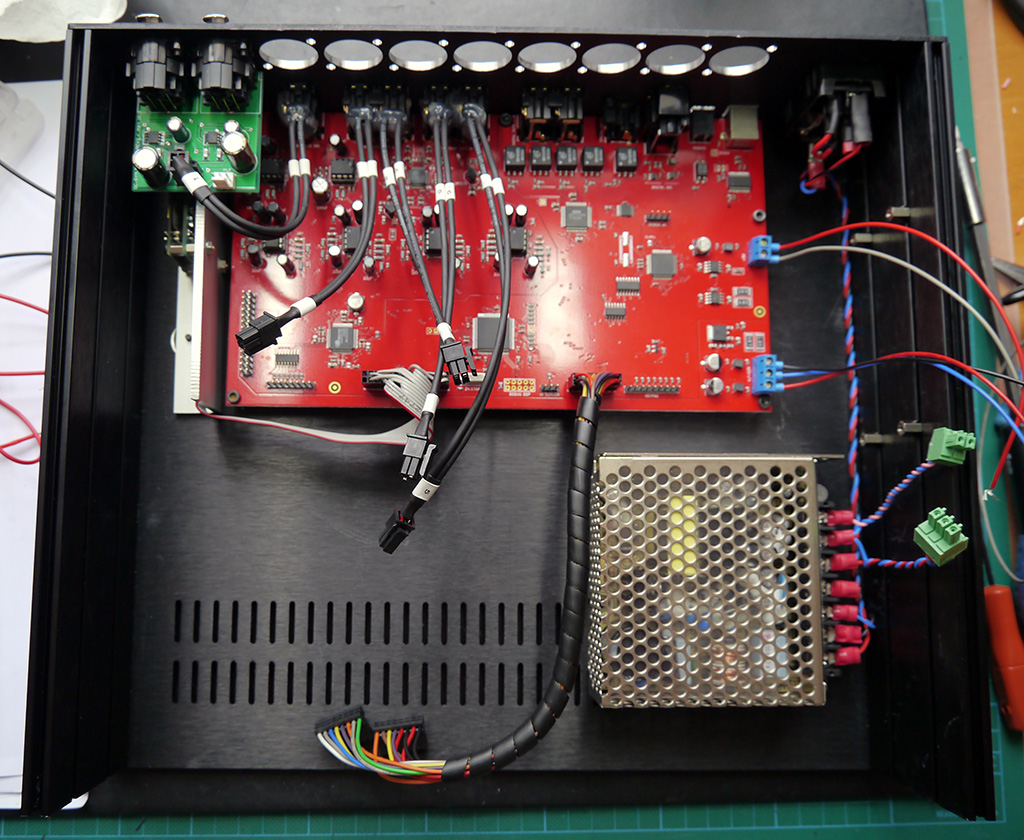
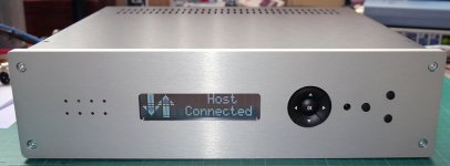
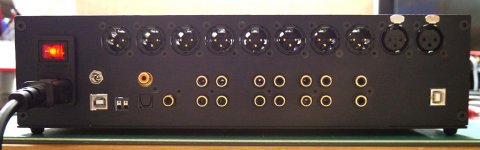
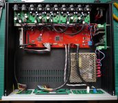
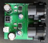
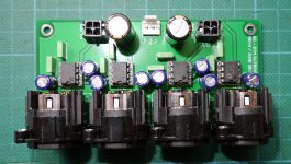
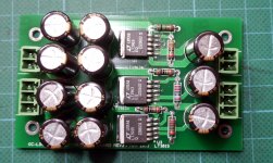
I've made some progress on my build. I'm still standing by for some pcbs to arrive from China to complete it
Jean Claude
Hey, Jean Claude
Where can i get these fine in/out xlr-pcbs?
Thanks
Nick, quick question,
Im using illuminated buttons for the controlpads. Each switch has an LED built in that draws 20ma @3v. In total there are 8 LED's.
Is it possible to power it them off one of the headers on the board?
Thanks.
Hi Beau,
I suppose you'd like to power these leds from the 5V supply rather than from the 3.3 regulated supply. Can you estimate how much current you would draw per led if you were using the 5V supply?
Hi Bruno,
The supply for the led backlight is 5V. So it's as above, you need first to estimate how much current you want to draw.
It's probably going to be necessary to add a current-limiting resistor in your both cases. Under this condition, yes, you can power the leds from the available supply onboard.
Nick
Hey, Jean Claude
Where can i get these fine in/out xlr-pcbs?
Thanks
Hi, I'm on travel right now. I'll give you details when I'll be back in a couple of days
Jean Claude
I was asked a question about Najda that I could not answer...
"I've currently got an asynchronous USB DAC, how would I incorporate this or any other device without USB output into the system and keep it asynchronous?"
I'm guessing it does not... What are the benefits of asynchronous in the real world?
"I've currently got an asynchronous USB DAC, how would I incorporate this or any other device without USB output into the system and keep it asynchronous?"
I'm guessing it does not... What are the benefits of asynchronous in the real world?
So like txt file it should work.
The curves might look kind of strange but I took them directly from nanodigi (minidsp) and they sounds fine.(PA woofer weak low end)
Except for the Q on the 70hz EQ should be 0.8 but it keeps jumping back to 3.00.
Just hope you can take the EQ from nano digi and use it in Nadja,that woofer curve did look strange..
Hi Ake,
I had a look at your file. The load is properly balanced between the 2 cores and I can't do anything to help. I have several ideas for optimizing the processing, so it might be possible to implement this setup at 192 kHz in the future.
Regarding the Q of shelving filter "jumping back to 3.0": Najda doesn't use the Q factor for these filters, but rather a S parameter, which is proportional to the slope achieved in the transition band in dB/oct. With this convention, the min value for S is 3.0 and the max is 12.0.
3.3 would be perfect, missed that. Have to take a look at the header pin out again.
I wouldn't do that. Using clean regulated supplies to power leds is a waste. The 3.3V supply is mainly intended for the DSP's IOs. These IOs must be powered before the cores get their 1.2V supply.
Also, here's a quick note about the staging of power supplies:
- When you turn on Najda, a certain amount of current goes through the 3.3V regulator.
- If you draw too much current, the 3.3V regulator will keep the 1.2V regulator in power down.
- The 1.2V regulator will tell the micro that it couldn't start.
- The micro will not boot the DSPs.
Frankly, I would do a couple of tests with a resistor in series with one led and a 5V supply. Keep raising the value of the resistor (you could use a pot) until you're happy with the amount of light the led emits. I suppose you want the buttons to be visible in the dark and that you don't want to illuminate your home with these leds, so you should be able to keep the current low.
Once you have determined the proper resistance value, you can measure the current per led. If you can keep it below 100 mA for all leds, then you can power them from the 5V supply.
I was asked a question about Najda that I could not answer...
"I've currently got an asynchronous USB DAC, how would I incorporate this or any other device without USB output into the system and keep it asynchronous?"
I'm guessing it does not... What are the benefits of asynchronous in the real world?
Hmmm... Honestly I don't understand the question me neither.
If it's just a DAC then you don't need it with Najda - Najda has its own set of DACs.
If the device outputs I2S, then you can connect it to Expansion Port 1 as explained in the manual and stream USB audio straight into the system. This is the preferred option.
If the device has SPDIF out, then you can connect it to one of Najda's SPDIF ins.
My understanding about this asynchronous stuff is that the data collected from the USB line is stored in a buffer and re-clocked onboard. In order to transfer the audio data to another device, you need to transmit a clock as well, so the transmission gets synchronous again. In clear, the asynchronous stuff applies only to the buffering part of the USB device; as soon as you want to use the data, it becomes synchronous again, whether you send it to the onboard DAC or transmit it to another device.
Hi Nick,
I've posted a few comments in post #1291 is it something that could be done??? I suppose it could but is it something that you may include in a near future???
Thank you
zoula
Ooops, indeed I skipped your post below.
I really like the new option about custom Biquad. It work ok, but I find it difficult to work with it since you can not from the software see the coefficients that you've enter. It is hard to see really what your doing. Plus there is no way to get you coefficients back once load in the card if you loose your text file. So, what I propose is to have a custom Biquad button that pop a new window with all the coefficients available. It would make adjustment more simple and easy.
Well I don't know. I can't imagine someone typing all the digits for all the coefficients - or even copying and pasting. That's very much error prone.
On the other hand, biquad coefs is not something that you can tweak manually: you need to run the computation again and import the new coefficients.
I however understand what you mean: once you've imported the coefficients, you can only look at the frequency response graph to identify which coefs you have loaded on each channel (note that you could also open the nsf file and check here your coefficients).
I had thought of displaying the coef file name in the setup panels but gave up on that for the following reason: if you modify the file and don't import again the new coefs, then the displayed file name doesn't point to the coefs being used.
I don't know what we can do, we need to think a little further. In any case that's probably a detail: as for now you can import the coefs and view the frequency and phase responses of your coef set. When you have a strong doubt you can still open the setup nsf file, the coefs are clearly displayed as in the example below (10 biquads):
Code:
<Channel Index="0" Source="Left" Pre_Gain="0.0" Post_Gain="0.0" Channel_Invert="0" Delay_Samples="0">
    <XOLP Type="0" CutOff="2000" Order="0"/>
    <XOHP Type="0" CutOff="500" Order="0"/>
    <EQ NumSections="10">
        <Section Type="-1" b0="0.282420306759421980" b1="-0.080995298981152999" b2="0.030521497616177999" a1="1.276247963471800000" a2="0.473684210526315990"/>
        <Section Type="-1" b0="0.868295148759569040" b1="-0.868295148759569040" b2="0.000000000000000000" a1="-0.736590297519136960" a2="-0.000000000000000000"/>
        <Section Type="-1" b0="0.806649233538374030" b1="-1.613298467076750100" b2="0.806649233538374030" a1="-1.576180556918350000" a2="0.650416377235152000"/>
        <Section Type="-1" b0="1.258925411794169900" b1="0.000000000000000000" b2="0.000000000000000000" a1="-0.000000000000000000" a2="-0.000000000000000000"/>
        <Section Type="-1" b0="1.009943679177649900" b1="-1.772507135379189900" b2="0.941848930696213000" a1="-1.772507135379189900" a2="0.951792609873866050"/>
        <Section Type="-1" b0="1.030188660630760000" b1="0.138622768091006990" b2="0.736627115220831020" a1="0.138622768091006990" a2="0.766815775851595990"/>
        <Section Type="-1" b0="1.026624199863180000" b1="-1.465339548271680000" b2="0.767724298581248020" a1="-1.465339548271680000" a2="0.794348498444431010"/>
        <Section Type="-1" b0="0.949884466592574970" b1="-0.523528316553325990" b2="0.418160952352727990" a1="-0.523528316553325990" a2="0.368045418945303020"/>
        <Section Type="-1" b0="0.996497225278577980" b1="-1.922977738712559900" b2="0.969440980029027010" a1="-1.922977738712559900" a2="0.965938205307604990"/>
        <Section Type="-1" b0="1.002360455852320000" b1="-1.950346853363710100" b2="0.986195951276735980" a1="-1.950346853363710100" a2="0.988556407129056010"/>
    </EQ>
</Channel>
Also the same way of doing thing could be done with the input and the output graph. This way you can check the progress of what your doing in real time.
Yes, undocking of the graph panels was requested several times. Need to look at that.
Also could it be possible to add custom biquad in the crossover section too. I realize that it could be done in the PEQ section but in the case that you want a 8 order low pass and High pass, it will eat up a lot of biquad coefficients, and leave you only 1 or 2 for filtering.
Yes, why not indeed. Or we could increase the number of biquads per channel. Or both. (Cross-overs in the EQ section is not the best idea because of the Bypass switch).
Best,
Nick
Hi Jean-Claude,
Well, what can I say? I'm speechless Thanks for posting the pics!
Hey JC
Alright, it's coming soon
Well, what can I say? I'm speechless
Thanks for posting the pics!Thanks,
now... waiting for mix FIR-IIR... Hey Nick
JC
Hey JC
Alright, it's coming soon
- Home
- Source & Line
- Digital Line Level
- DSP Xover project (part 2)