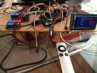
The backlight dimming has worked, the 3.3v & 5v connections from the Mega to the Shield are still in place, the 5v goes via a relay which switches when I turn the system on.
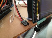
I have bent the LED pin on the screen at 90 degrees, cut a small slot in the shield 40 pin socket so the screen still plugs all the way in. I have then soldered on a lead to the LED added 2 resistors in series/parallel, to get 54 ohms, put a plug on the end of the lead & plugged it into the Mega 7 pin.
I have written the code so the backlight turn on at a defined brightness & can be adjusted with the left button on the Apple Ring, when I put it into sleep mode the backlight dims to defined value & turns back up if the sleep function is aborted. When the system is turned off the backlight is lowered to 0 volts.
BUT , why is there always a but? For some mystical reason the addition of the backlight dimming is playing havoc with the remote reception. After much grief I finally go the remote working every time but now it is back to misbehaving, could it be something to do with the PWM voltage that is now in the system, any advice would be greatly appreciated.
I have bent the LED pin on the screen at 90 degrees, cut a small slot in the shield 40 pin socket so the screen still plugs all the way in. I have then soldered on a lead to the LED added 2 resistors in series/parallel, to get 54 ohms, put a plug on the end of the lead & plugged it into the Mega 7 pin.
I have written the code so the backlight turn on at a defined brightness & can be adjusted with the left button on the Apple Ring, when I put it into sleep mode the backlight dims to defined value & turns back up if the sleep function is aborted. When the system is turned off the backlight is lowered to 0 volts.
BUT
, why is there always a but? For some mystical reason the addition of the backlight dimming is playing havoc with the remote reception. After much grief I finally go the remote working every time but now it is back to misbehaving, could it be something to do with the PWM voltage that is now in the system, any advice would be greatly appreciated.Attachments
AFAIK when you change the parameters for a specific input, they are saved in an array and at the EEPROM. When you switch inputs, the specific parameters are recalled and applied. I'm talking about input type (s/pdif vs. i2s) etc.
Yes, that's another function to detect SPDIF and I2S and set the specific parameters accordingly. Not the bug I found.
HiFiduino's code setAndPrint all other parameters every time after the setAndPrintInput, so all other parameters will be changed when selecting input since all these function use "input" as the reference value for "CASE" selection. I remove those setAndPrint from setAndPrintInput and put them into a new "refresh ALL" function.
The backlight dimming has worked, the 3.3v & 5v connections from the Mega to the Shield are still in place, the 5v goes via a relay which switches when I turn the system on.
I have bent the LED pin on the screen at 90 degrees, cut a small slot in the shield 40 pin socket so the screen still plugs all the way in. I have then soldered on a lead to the LED added 2 resistors in series/parallel, to get 54 ohms, put a plug on the end of the lead & plugged it into the Mega 7 pin.
I have written the code so the backlight turn on at a defined brightness & can be adjusted with the left button on the Apple Ring, when I put it into sleep mode the backlight dims to defined value & turns back up if the sleep function is aborted. When the system is turned off the backlight is lowered to 0 volts.
BUT
Will try to isolate the LED pin from Arduino Shield during the weekend and advise you the result. I realize that you connect both 5V and 3.3V from Arduino to the shield, you should only connect either one. If you connect the 5V, then put the switch on the shield to 5V and the regulator on the shield will convert it to 3.3V for the LCD. If you connect both, then you still have 3.3V supply to the LCD even you disconnected the 5V.
In that case, I am not getting what the bug was. Could you be a little more specific or better yet, post some code?
Yeah, I am most interested in this bug
. The way it is currently programmed (as dimdim said) is that every input has independent settings for each function, and they are saved in eeprom. When you switch to another input, the settings are recalled from the eeprom and programmed into the registers. Granted, not all of the them would change, but it was easiest to just rewrite all the values into the registers everytime you change inputs.The backlight dimming has worked, the 3.3v & 5v connections from the Mega to the Shield are still in place, the 5v goes via a relay which switches when I turn the system on.
I have bent the LED pin on the screen at 90 degrees, cut a small slot in the shield 40 pin socket so the screen still plugs all the way in. I have then soldered on a lead to the LED added 2 resistors in series/parallel, to get 54 ohms, put a plug on the end of the lead & plugged it into the Mega 7 pin.
I have written the code so the backlight turn on at a defined brightness & can be adjusted with the left button on the Apple Ring, when I put it into sleep mode the backlight dims to defined value & turns back up if the sleep function is aborted. When the system is turned off the backlight is lowered to 0 volts.
BUT
Very nice!
I too had some problems with the remote when using analog write. I was not able to find the reason, so I gave up controlling the brightness with the Arduino and used a manual pot. It is possible, the pulsating LCD is creating a lot of noise and interfering with the IR sensor. I documented some issues here: Apple Remote Control for Buffalo II DAC H i F i D U I N O
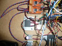
BTW, what are those small orange boards?
I remove the pin 19 for LED and solder a 47ohm resistor. Use Arduino analogWrite to control LED On/Off/Dim without any problem.
Pin 19? must be a different screen, mine is pin 37
Very nice!
I too had some problems with the remote when using analog write. I was not able to find the reason, so I gave up controlling the brightness with the Arduino and used a manual pot. It is possible, the pulsating LCD is creating a lot of noise and interfering with the IR sensor. I documented some issues here: Apple Remote Control for Buffalo II DAC H i F i D U I N O
BTW, what are those small orange boards?
Thanks, I'm glad it's not just me.
The orange boards are Tinkerkit Mosfet relays, they are switching the relays I had already installed into my amp & DAC.
Pin 19? must be a different screen, mine is pin 37
We are using the same screen, look at the marking of the board, your pin no should be 19.
We are using the same screen, look at the marking of the board, your pin no should be 19.
Yes you are right, I was forgetting how the numbers went
Removed the pin connecting LCD screen and Arduino Shield, solder a 47ohm resistor in series and connect to PWM pin. Screen dimming and off are working fine. Other functions including remote are working as expected. Number of relays increase from 2 to 6 and seems still not enough
Attachments
Yeah, I am most interested in this bug
I go through the original HiFiDuino's code again and have a different view. There is no specific format for each input, you just have to assign a name for it. So it is not possible for the code to know whether input #1 is SPDIF, PCM or DSD. The code only read the SPDIF status register to determine whether the source is SPDIF or DSD.
I successfully modified the BIII to run in synchronized mode with FIFO. The sound is lot more dynamic with more details. Thanks Ian.
But Synchronize mode cause a new problem, Arduino can't display the correct clock frequency
Where are you determining fs? For waveio you can use its output header...
I successfully modified the BIII to run in synchronized mode with FIFO. The sound is lot more dynamic with more details. Thanks Ian.
But Synchronize mode cause a new problem, Arduino can't display the correct clock frequency
Hi,
Like your setup with Ardunio.
Where are you determining fs? For waveio you can use its output header...
HiFiduino's code read the register in the BIII and then divided by an integer which was calculated based on the crystal frequency. I am not sure whether Ian's clock board output fixed frequency or will be changed based on the SF of the source
Thanks for your suggestion, but it only indicate the frequency when using USB:-(
Last edited:
cant you still read the register on the BIII? fifo MCLK is fixed frequency (1 or 2 depending on if you are using single or dual clock board) the BIII will use BCLK which changes with FS, not MCLK I would think. the info presented to the BCK pin on ESS will be the same whether you use the onboard clock, or fifo in sync mode
Last edited:
- Status
- This old topic is closed. If you want to reopen this topic, contact a moderator using the "Report Post" button.
- Home
- Source & Line
- Digital Line Level
- Build Thread for TPA BIII + Ian Async I2S FIFO + OPC NTD1 + Salas SSLV