a spreader is not often a good idea, it doesnt actually make anything more efficient, rather less efficient. Jan was kind enough to put that article online free. its written for the F5X by EUVL, but translates to pretty much any thermal dissipation solution.
weird, I somehow deleted a line I wrote. basically thanking Patrick for putting together such a thorough and excellently written, well researched article on a not often covered topic. Heatsink RTH rating and how the placement and spacing of devices across the heatsink relates to it, along with how it matters to us for audio using power devices in Class A. Thanks Patrick!
weird, I somehow deleted a line I wrote. basically thanking Patrick for putting together such a thorough and excellently written, well researched article on a not often covered topic. Heatsink RTH rating and how the placement and spacing of devices across the heatsink relates to it, along with how it matters to us for audio using power devices in Class A. Thanks Patrick!
Last edited:
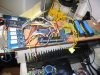
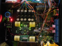
When I bought this power amp case for the DAC, I thought it should have plenty of space to accommodate everything, but when I have all the devices in hand, I find that I was wrong.
With the transformers, NTD1, SSLV, FIFO and BIII, there left no space for the Arduino, relay boards, battery, some more regulators ....
I haven't tested the 5V supply on the NTD1, I connected a 12Vac to the input and power it up. It has 4.99V output, but within one minute, the PCB near one of the diode burnt, found one diode shorted and another one broken. Other components seems fine. Have to repair the PCB and order some replacement diode and test again.
As the BIII will be powered by SSLV, I will modify the 5V supply on NTD1 to 10V for the Arduino, with a secondary regulator to power the 5V relay boards.
Still have a long way to finish this project.
With the transformers, NTD1, SSLV, FIFO and BIII, there left no space for the Arduino, relay boards, battery, some more regulators ....
I haven't tested the 5V supply on the NTD1, I connected a 12Vac to the input and power it up. It has 4.99V output, but within one minute, the PCB near one of the diode burnt
, found one diode shorted and another one broken. Other components seems fine. Have to repair the PCB and order some replacement diode and test again. As the BIII will be powered by SSLV, I will modify the 5V supply on NTD1 to 10V for the Arduino, with a secondary regulator to power the 5V relay boards.
Still have a long way to finish this project.
Attachments
I know mate - it's amazing how quickly a case will fill up. I ended up with a 16in x 11in x 6in tall; i needed the height and a second deck to fit it all You'll probably hate to hear this, but I'm testing an Amanero board + Acko reclocker using Ian's si570 board for the reference clock. The si570 & reclocker/isolator is battery powered, using Ian's Battery Management board to manage. It's replacing a full FIFO stack (FIFO, Isolator, si570) + an larger USB receiver (eXD), + and OttoII to switch off I2S/DSD.
I have to say - the new source components sound pretty damn good, and I get the benefit of DSD isolation/reclocking too. I'll give it some play time, but these components make for a simpler chain, fewer components, less space needed. The Amanero + Acko's reclocker/Isolator combination is a fantastic value so far.
You'll probably hate to hear this, but I'm testing an Amanero board + Acko reclocker using Ian's si570 board for the reference clock. The si570 & reclocker/isolator is battery powered, using Ian's Battery Management board to manage. It's replacing a full FIFO stack (FIFO, Isolator, si570) + an larger USB receiver (eXD), + and OttoII to switch off I2S/DSD.I have to say - the new source components sound pretty damn good, and I get the benefit of DSD isolation/reclocking too. I'll give it some play time, but these components make for a simpler chain, fewer components, less space needed. The Amanero + Acko's reclocker/Isolator combination is a fantastic value so far.
my case is just a little smaller than yours, 12in x 13in x 4.5in tall. I also plan to stack some devices and hope can fit it all.
I have both the WaveIO and Amanero. WaveIO will connect to FIFO TTL input. Amanero with two OTTO, connect to FIFO when not DSD and direct to BIII for DSD.
It will be great if you can show me the connection between Amanero, Acko reclocker and si570.
I have both the WaveIO and Amanero. WaveIO will connect to FIFO TTL input. Amanero with two OTTO, connect to FIFO when not DSD and direct to BIII for DSD.
It will be great if you can show me the connection between Amanero, Acko reclocker and si570.
I have to say - the new source components sound pretty damn good, and I get the benefit of DSD isolation/reclocking too. I'll give it some play time, but these components make for a simpler chain, fewer components, less space needed. The Amanero + Acko's reclocker/Isolator combination is a fantastic value so far.
MisterRogers, did you start a thread on your Amanero/Acko islator/reclocker setup? If not, how about starting one? If it works out many of us would be very grateful, if it doesn't work out then it's documented for others not to go that way?
Thanks
It's very straightforward mate; last page or so of the Amanero reclocker GB thread, Acko posts some PDF's showing various implementation configurations. I'm currently running the the config with the si570 mastering both the RCLK/Reclocker and the BIIISE. I'm not powering up the onboard clock on the Buffalo, using the si570 clock instead.
My reclocker build is the SO2 board using the potato semi flip-flop, with isolator. Worked right away, and the lock is rock solid.
My reclocker build is the SO2 board using the potato semi flip-flop, with isolator. Worked right away, and the lock is rock solid.
I mean for all of the power supplies. poweramp cases arent always that large on the inside, as the sides include large heatsinks, which you havent used, so they just take up space.
I dont think you can drill the Ti regs, you might be better off getting some polymer putty to squeeze onto the corners to give a mounting arrangement.
this stuff is excellent sugru
I dont think you can drill the Ti regs, you might be better off getting some polymer putty to squeeze onto the corners to give a mounting arrangement.
this stuff is excellent sugru
Last edited:
why arent you utilizing the heatsinks on your case BPHK?
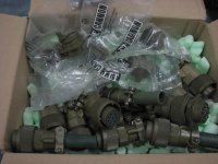
AR2 I prefer these which i'll also be using for the speakers
Yes, I use those as well. That is exactly I had on my mind in addition to SCII cables. I used one with 40 pins. For that I have to say, the best friend is Excel. The key is having a good list linking wire color codes and voltages.
Qusp, that was an awesome link for Sugru. I used something like liquid rubber, or paintable rubber, forgot the real name, but with sort of similar properties as Sugru. I found it very useful to make my own cable grummets. If I drilled the hole in the metal, it was great to paint that rubber around the edge to protect wires from being cut. Sugru seems even much more versatile and better. Thank you, outstanding find.
@ BPHK: I know, that was my point, the poweramp chassis is only large if you can make use of the heatsinks, otherwise they just take up volume. Its done now though and it'll still fit i'm sure, it'll leave plenty of heatsink for if you want to go OTT shunts
trace repair, I would just use a wire, or some copper foil if you can.
@ AR2: yeah the sugru is handy as hell for mounting stuff, strain reliefs etc. you can set bumpers, or even attach threaded standoffs with it. whatever you like and it even has mild damping properties, though perhaps a bit too bouncy for clocks etc.
Last edited:
MisterRogers, did you start a thread on your Amanero/Acko islator/reclocker setup? If not, how about starting one? If it works out many of us would be very grateful, if it doesn't work out then it's documented for others not to go that way?
Thanks
I know others will be pursuing an identical setup, so rather than start a thread - I'll post as appropriate to the Reclocker thread
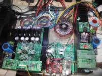
Drilling holes to fix all those PCBs is extremely time consuming. It is also difficult to ensure all holes are at the correct position. Except the USB input devices which will be mounted directly on the back panel, I should have mounted all other devices into the case and its time to connect them together.
I tested all the PSUs and they are all working fine. Then Ian's FIFO + i570 + SPDIF also working properly. The Arduino and relay boards are also OK. It's time to mount the BIII onto the NTD1
Before mounting the BIII, I measure all the voltage on the NTD1 again. One of the Vs dropped to 0.3xxV, others are 1.5xxV. I thought the VR was adjusted accidentally, but when I turned the VR fully to both direction, the voltage only vary between -2.xxV to 0.8xxV
I really upset, something failed again. Power off it and measure the FET, found low resistance from G to GRD. If the FET fail, I have to replace all four FET with the spare set
to check the FET, I have to desoldered it from the PCB, but remove the PCB from the heatsink is not easy. Putting it back after trouble shooting is a painful job.
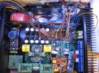
Spent almost a month to figure out how to put all the devices into the case and finally, I believe it can be done.
Also spent two weeks to trouble shoot the NTD1 and thanks Owen helped me to discover a stupid mistake (again)
Looks awesome
. It's amazing you integrated everything together!Ian
Thanks Ian.
Spent an hour to remove the heaksink from the case and the PCB from the heaksink. Desoldered the FET and found it still alive So it would be either the VR or the cap fail. Desoldered the VR and confirmed it's also fine. I thought ceramic cap is very reliable and would not fail. Measured the cap several times and confirmed that it's dead with a low resistant of 1xx ohms.
I don't have the same type of 10u cap, so replaced it with another 10u with higher voltage. Hope this wouldn't affect the sound.
Put the NTD1 back to the case, check everything again and connect all wires for control and signal. Power it up. No smoke
Fed signal to Optical in, BIII lock, mute LED off, so far so good. Still hasn't connect the audio output, need fine tune on the Arduino program and connect Arduino with i570, final will be the drawing for front panel express
Spent an hour to remove the heaksink from the case and the PCB from the heaksink. Desoldered the FET and found it still alive
So it would be either the VR or the cap fail. Desoldered the VR and confirmed it's also fine. I thought ceramic cap is very reliable and would not fail. Measured the cap several times and confirmed that it's dead with a low resistant of 1xx ohms. I don't have the same type of 10u cap, so replaced it with another 10u with higher voltage. Hope this wouldn't affect the sound.
Put the NTD1 back to the case, check everything again and connect all wires for control and signal. Power it up. No smoke
Fed signal to Optical in, BIII lock, mute LED off, so far so good. Still hasn't connect the audio output, need fine tune on the Arduino program and connect Arduino with i570, final will be the drawing for front panel express
Attachments
- Status
- This old topic is closed. If you want to reopen this topic, contact a moderator using the "Report Post" button.
- Home
- Source & Line
- Digital Line Level
- Build Thread for TPA BIII + Ian Async I2S FIFO + OPC NTD1 + Salas SSLV