qusp; said:lol, his DAC is 'completed' did you read that boys? if you do not cancel your account here at the forum, I doubt very much that will be the case
Sorry for poor English .
both connected to fifo? off-ramp (spdif?) will be transformer isolated. I notice you havent got the isolator on fifo, yes Amanero does directly couple noise from the PC; without any isolation it can be a little noisy.
Yes, both connected to FIFO. Empirical Off-Ramp 3 connected to FIFO via Coaxial and Amanero via I2S backdoor.
Sorry for poor English .
Yes, both connected to FIFO. Empirical Off-Ramp 3 connected to FIFO via Coaxial and Amanero via I2S backdoor.
Compared to my Vietnamese your English is bloody good

haha sorry, no its me and my bad sense of humor, your English is perfectly fine, it was me who was not clear, my post was not meant to ridicule you in any way.
I mean only that you have started a road that usually does not end so swiftly. if you finish your DAC now, that would be a miracle and would make you a stronger man that I am (not so difficult).
its perfectly fine as it is and better than the majority of pretty high priced commercial DACs, you could put it in a case and it would be a very nice DAC. but most people who get to the point you are at now, are already beyond the point of no return. normally they are already thinking of something else that they 'need' to add.
if you did stop now, I would be very impressed with your resolve.
Run while you still can!
but most people who get to the point you are at now, are already beyond the point of no return. normally they are already thinking of something else that they 'need' to add.
That's exactly my situation right now.
I "completed" the DAC almost six months ago but I still get tons of upgrade going on. I570, NTD1, Amanero isolator....., casing will be final step to finish the DAC
Yea, it's been my experience that I can't seem to leave my DAC(s) alone. I've settled on my 'go to' amps and headphones (bridged SE wires, Mjolnir, HE-5's modded). There always seems to be one more thing to try, and there's still more sonically to gain.
All - If you're not running some sort of isolation, you need to be. Ian's FIFO with good clocks and the Isolator are stellar. I'm waiting for the si570 clock boards, plus working up a battery system, then I'm not sure where to go from there
I've been driving my DAC with an S11, and this weekend I thought I'd configures one of my TPS7A4700's for 5v and place it in series. I need to listen for a bit longer, but there's more subjective detail/blackness. At this level it's hard to say, but it certainly didn't do any harm
@DQ828 :
Thank you for your sympathy.
@qusp :
No problem ,a sad moment but I think you misunderstood. I'm not an electronics engineer, but I love music and enter into the DIY movement .I did some audio projects for myself, but this is the first time I DIY DAC, so very thanks if get your share.
I had good results with Buffalo IIISE + Ian Async FIFO and continue with module usb input . I am waiting the component from digikey for clock isolator, i2s isolator . I like Ian's project .
Last edited:
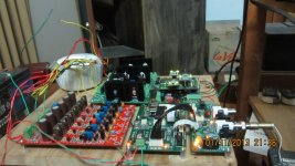
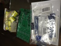
A big step ahead to the "completion of my DAC" project. Received the PCB, caps, Zfoil and FETs from qusp. Thanks for all the great contribution from Owen, Jeremy and Buzzforb for this GB.
With the components that I bought six months ago, I can start building the NTD1 now. With Ian's I570 on its way here and Acko's isolator/reclocker to be delivered within this month. Hoping to have everything connected and test in March.
With the components that I bought six months ago, I can start building the NTD1 now. With Ian's I570 on its way here and Acko's isolator/reclocker to be delivered within this month. Hoping to have everything connected and test in March.
Attachments
you cant attach directly? remember adding any thermal interface, no matter how good, makes the performance worse, not better and you will be adding at least 2. also can you guaranty that the copper will be perfectly flat? if its not you will not have good thermal contact and could burn a part.
one tip for this build, use PCB material or similar as shims for the zfoils to make all the parts level and just initially attach to the heatsink with just the 4 main holes. the legs on the zfoils are quite thin and if one of your screws catches in one of the wholes as you are attaching, or removing from the heatsink it will lift up and can break, even if you go around loosening each screw a couple turns at a time. once fully tested you can add the screws through the parts if you wish
one tip for this build, use PCB material or similar as shims for the zfoils to make all the parts level and just initially attach to the heatsink with just the 4 main holes. the legs on the zfoils are quite thin and if one of your screws catches in one of the wholes as you are attaching, or removing from the heatsink it will lift up and can break, even if you go around loosening each screw a couple turns at a time. once fully tested you can add the screws through the parts if you wish
no, I mean
mosfet/resistor->keratherm->heatsink
has 2 less interfaces and thus less thermal impedance vs
mosfet/resistor->keratherm->copper->thermal grease or keratherm->heatsink
heat spreaders are always a worse performing solution vs direct connection, it doesnt matter if its copper or not (even silver), it will always create more thermal resistance.
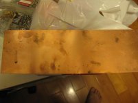
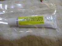
not that copper, it doesnt look very flat and can bend during use pretty easily at only 2mm and unless you can get very good contact it'll be much worse than the floor. depending on the case the floor may be enough by itself, its certainly easier. you dont need it for the zfoils, but I still use it, just because it gives a good even connection. you could use thermal grease, silver or ceramic paste, but they get messy and most dry out and need changing every now and then. you need something, cant just connect directly, it wont make good thermal contact.
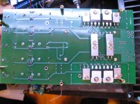
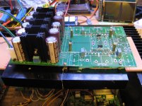
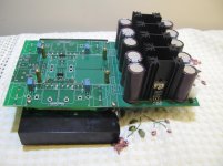
The Heaksink of my case is not high enough for the NDT1 to mount on it directly. I have to try my initial plan to use the copper plate as heat pipe.
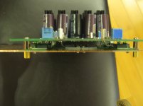
Spent several hours to drill holes and fixed the PCB onto the plate. Checked all FETs and zfoil no short, then power up, no smoke.
PSU output between 44.95 - 45.03V, DC at output around 22.6V. Everything seems working. The temperature raises to 55 deg C within several minutes.
The heat conducting of the copper is far worse than expected. The portion attached with FETs follow the temperature of the FET but remain at 30 deg. C at the other end.
Don't want to fix it onto the case floor at the moment, I have to carefully plan how to place so many devices into the case.
Attachments
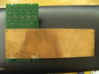
just means you dont need the heatsink, the copper and air is doing a good job getting rid of the heat by itself before it conducts to the other end, which I would expect with that much surface area, just have to watch bending it so contact stays good.
its actually flatter than I thought too, the oxidizing on other side makes it look less level than it is.
its actually flatter than I thought too, the oxidizing on other side makes it look less level than it is.
Last edited:
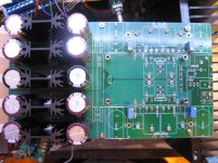
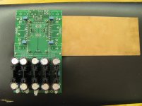
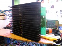
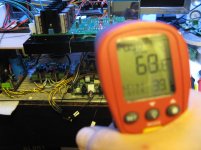
Replaced the copper plate with heatsink but the size is too small, the temperature raised to near 70 deg and still going up. double the size by using heat transfer glue to stick two heatsinks together.
After power for half hour, temperature stabled at 68.x deg.
After power for half hour, temperature stabled at 68.x deg.
Attachments
- Status
- This old topic is closed. If you want to reopen this topic, contact a moderator using the "Report Post" button.
- Home
- Source & Line
- Digital Line Level
- Build Thread for TPA BIII + Ian Async I2S FIFO + OPC NTD1 + Salas SSLV