Thanks ch33ta, i made Your project and it works fine. For analog i use 6n6p cathode follower ala lampizator directly from cs4398 because i use tube amp. Some time ago i had stock cs4398 dac without any power supply modifications and i can tell that with Your mods sound is simply better. One again many thanks for Your tutorial, Best Regards
now i can not buy CS8416, can i use CS8414 + CS4398 ?
Yes you can, but keep in mind that CS8414 uses 5V power supply, not a 3.3V like the CS8416.
I´m bumping this thread 
This is my version of this kit:
- improved Capacitor values for the power supply ( purchased high quality Capacitors from Panasonic, low ESR )
- purchased 2,5% tolerance Wima FKP2 for the output buffer
- inserted a LME49720 instead of the supplied NE5532
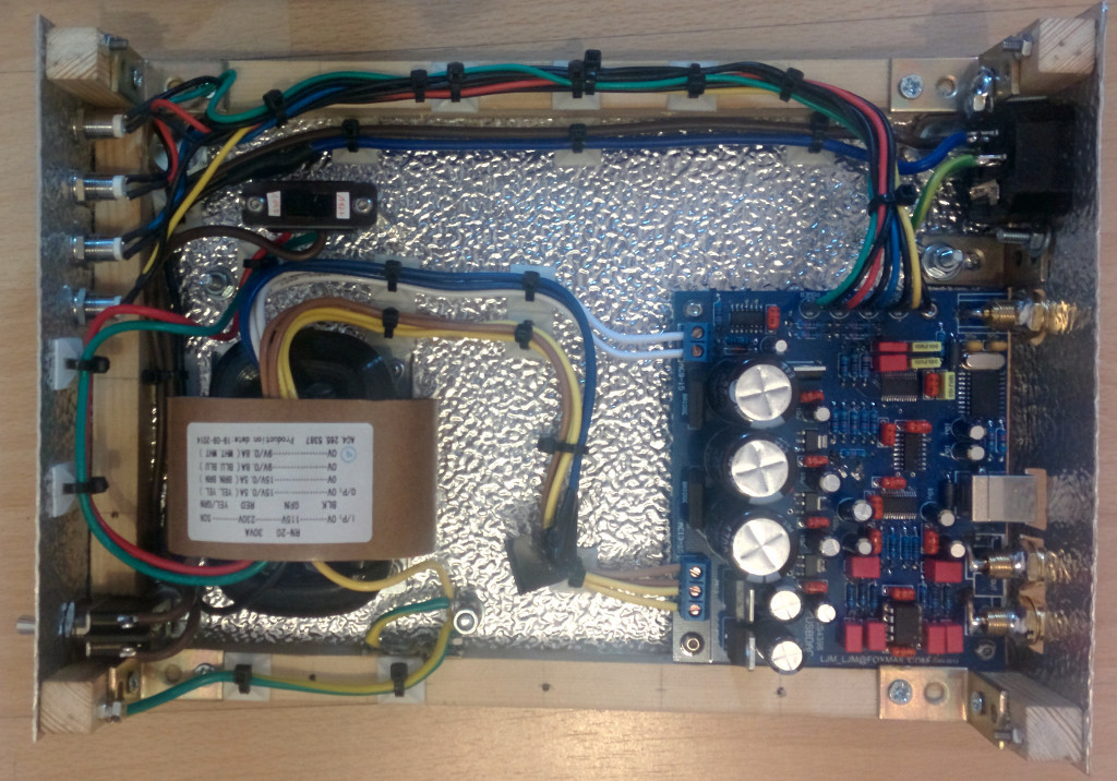
I only used some of the supplied components like eg. the terminals, rectifiers, 1% precision resistors etc. and only upgraded the values on the board where necessary.
In order to make sure that I do the right thing, I also checked the datasheets of the regulators. It´s no use if you try to eg. insert a 10000000000µF cap instead of a 10µF input capacitor for the 3,3V and 5V voltage regulators.
My device has no audible hum and I like the sound. I don´t have the equipment though to perform a advanced analyze of the circuit itself, check the THD etc.
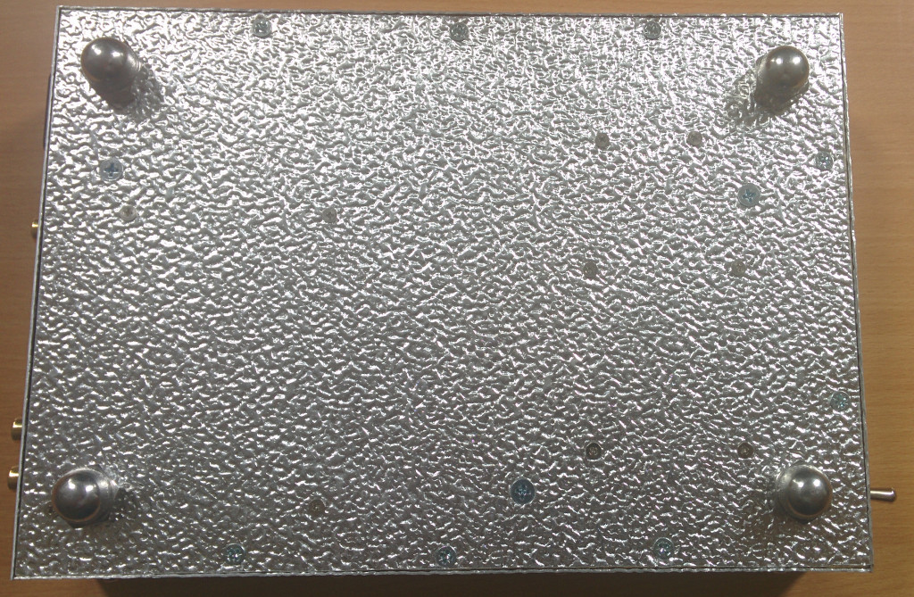
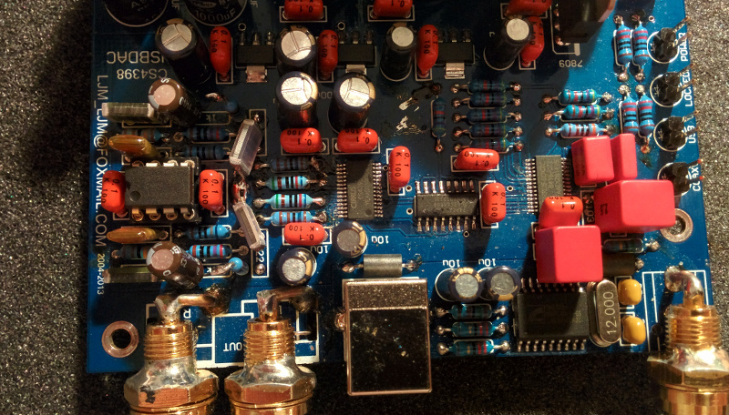
Here are some pictures
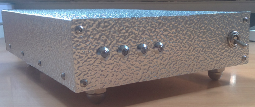
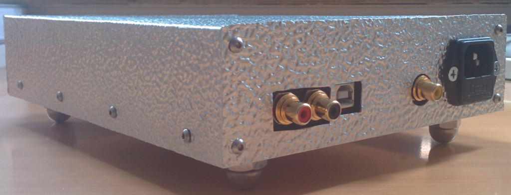
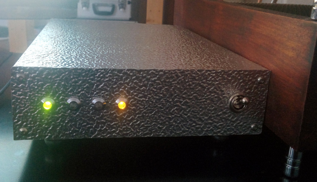
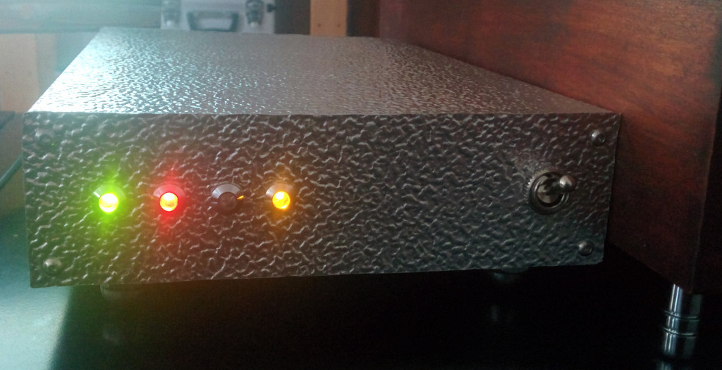
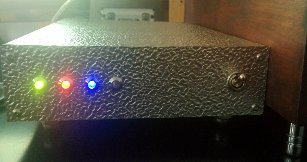
I used a different color scheme for my device instead of 4x blue LEDs:
power: green
signal locked: red
SPDIF: yellow
USB: blue
Best regards,
This is my version of this kit:
- improved Capacitor values for the power supply ( purchased high quality Capacitors from Panasonic, low ESR )
- purchased 2,5% tolerance Wima FKP2 for the output buffer
- inserted a LME49720 instead of the supplied NE5532
I only used some of the supplied components like eg. the terminals, rectifiers, 1% precision resistors etc. and only upgraded the values on the board where necessary.
In order to make sure that I do the right thing, I also checked the datasheets of the regulators. It´s no use if you try to eg. insert a 10000000000µF cap instead of a 10µF input capacitor for the 3,3V and 5V voltage regulators.
My device has no audible hum and I like the sound. I don´t have the equipment though to perform a advanced analyze of the circuit itself, check the THD etc.
Here are some pictures
I used a different color scheme for my device instead of 4x blue LEDs:
power: green
signal locked: red
SPDIF: yellow
USB: blue
Best regards,
Hello,
I was wondering if anyone could help me; my board has been dead for longer than I care to think about. I think the problem is a short to ground - if I measure the resistance to ground from the output of the top (in Gorgomat's 4th pic above) 3.3v regulator then it is just 57 ohms! Am I right in thinking that that's bad?
I've been systematically de-populating my board and have got to the point where I've removed all of the caps that I think are downstream of that regulator. However, the resistance to ground stubbornly remains at 57 ohms. (I've removed the 3.3v reg as well and there's no short to ground from the input to it.)
I'm beginning to wonder whether one of the ICs has failed. Anyway, if someone could clarify whether I'm on the right trail that would be great.
Thanks very much,
Andy.
Hello,
I´m not sure if I understood your question the right way but I can try to help you Can you eg. post a picture of the PCB with the area marked, of what exactly you tried to measure ?
I can check my board too and measure the values too since it´s not quite a big deal for me to remove it out of my case
I will also need some help from guys who are more experienced than me, when it comes to designing output stages made with Opamps..
I want to stick to my LME49720 Opamp and build a extra output stage, based on the recommended topology in the cs4398 datasheet. I have some trouble though, calculating the resistors and capacitors for exactly this Opamp..
I know that in order to connect the "new stage" with this PCB, I will have to remove the Output buffer ( resistors, capacitors, socket etc. ), create a extra PCB and mount it on top of the LJM PCB and connect everything manually ( +- 12V, GND , inputs, outputs ).
Best regards,
I´m not sure if I understood your question the right way but I can try to help you
Can you eg. post a picture of the PCB with the area marked, of what exactly you tried to measure ?I can check my board too and measure the values too since it´s not quite a big deal for me to remove it out of my case
I will also need some help from guys who are more experienced than me, when it comes to designing output stages made with Opamps..
I want to stick to my LME49720 Opamp and build a extra output stage, based on the recommended topology in the cs4398 datasheet. I have some trouble though, calculating the resistors and capacitors for exactly this Opamp..
I know that in order to connect the "new stage" with this PCB, I will have to remove the Output buffer ( resistors, capacitors, socket etc. ), create a extra PCB and mount it on top of the LJM PCB and connect everything manually ( +- 12V, GND , inputs, outputs ).
Best regards,
Hello,
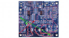
Attached is cheeta's x-ray view of the board. I've highlighted the output of the 3.3v reg with a red arrow and two of the ground locations with green arrows. I measure a resistance of 57 Ohms between the point with the red arrow and either of the points with green arrows (one of these is the heat sink of the 7809 reg). It would be great if you could tell me what you measure.
In looking at that pic I've realised that I haven't removed the large caps taking care of the PSU. I don't think they're implicated but I'm pretty new to this and they're the only original caps left so I'll try taking them off tomorrow. (I changed the majority of the caps after the board failed but without success.)
Thanks again,
Andy.
Attachments
Hello,
I measure a ohm resistance of about 477 Ohm between your marked points. The red arrow points on the Vout tap of the regulator.
57 Ohm measured against ground looks indeed like a short circuit.
Now here´s the deal: next to the voltage regulator you will find a 100nF capacitor and a 10µF capacitor. I would try to remove both of them and also measure them, if one of them is damaged ( such a error is very rare but not impossible ).
If you have removed both capacitors but can still measure this low resistance, the regulator might be fried and needs to be replaced.
If you´ve already removed the regulator and can still measure this resistance, we need to have a closer look at the components around Pin 13 and 14 of the 74HC04
The 1N4148 Diode, the 100k resistor, the 100nF capacitor and the 1µF capacitor, if you can still measure a error.
Ofc this regulator also feeds the CS8416 at Pin 23 and you need to check the components too:
the 47k resistor between Pin 23 and Pin 20, the capacitor between Pin 23 and Pin 22.
Like I mentioned before, we´re dealing with quite low voltages in this device and it is hard to believe that maybe one of these components is damaged but at least I would suspect the regulator to be fried. And I sure hope that the ICs itself are not fried too.
How exactly did the board die ?
Best regards,
Last edited:
Hello,
Thanks for getting back to me.
I've removed the regulator and the caps next to it but that didn't change anything. (In fact, I originally replaced the regulator altogether but that didn't make any difference.)
I then removed the 1N4148 diode and the 100nF and 1uF caps near the 74HC04 and that too had no effect.
I've also removed the cap between pins 23 and 24, again without effect.
Up to now I've been assuming that if anything had failed it would be a cap so I haven't tried removing the resistors - I'll have a go at that as soon as I get some time.
The board had been working fine until I left it on overnight and then it would no longer give any audio output - the 'coax' and 'locked' LEDs would light appropriately but that was it. The three large 2,200uF caps were getting very hot. I then replaced all of the 104 caps as I suspected an oscillation in the voltage regulation. This stabilised the voltages and I could find nothing obviously incorrect apart from the fact that I was getting no output and that the 7809 reg. was getting very hot. At this point I started taking things off the board and discovered the short to ground.
Perhaps it will prove to be a problem with one of the resistors - fingers crossed! I'm suspicious of the quality of the components supplied with the kit as the op-amp was dead on arrival.
Thanks,
Andy.
Hello,
now comes the tricky part. I under stood right that though you have removed the voltage regulator and the other components, you can still measure this low resistance ?
Ok, maybe one of the ICs is damaged, or even both but there is a tricky way to find out:
Follow the connection from the Vout, to the 74HC04 and make sure to use a sharp knife, in order to interrupt it ( but make sure that you chose a good distance from the IC so you can still have a chance later, to reconnect the lane with solder ! ).
Now you have no direct connection to the 74HC04 and assuming that you have soldered a "fresh" regulator on the PCB, we can measure the resistance again.
If you still measure this low resistance, we need to do the same, interrupt the trace which leads to the CS8416, Pin 23. ( Also make sure that you chose a lane where you have again the possibility to reconnect the cut again ).
If you measure a higher value now, you might have found yourself a damaged CS8416.
This method is not very clean but it can help to find out if the ICs are damaged.
Lucky for me that I used other components but I also noticed that the capacitors run quite hot.
Well, I did some advanced measuring and I can spot indeed some sort of RF overlay on top of a 1kHz Sinus, directly out of the CS4398.
Now I will try to build myself a power supply filter and also see if I can find a way order to suppress the oscillations.
You can use some ferrite beads on the output of the 7xxx regulators.
I will take pictures of my scope, the next time I have to fiddle around with it
Best regards,
Last edited:
Btw, there is another trick to stabilise the voltage of the 7xxx regulators. If you have a closer look at their datasheets, it is mentioned that they need a current flow of at least 5mA in order to function properly.
Well, assuming that the Opamp really needs next to nothing in order to work ( check the datasheet of the Opamp you want to use ), we need to force the regulators to still have at least a current of min. 5mA pass through them.
For the 7x12 regulators we would need a resistor , parallel to the capacitor of the output of at least 2400 Ohm. ( R = U / I ---> 12V / 0,005A ).
Using eg. a resistor of eg. 1200 Ohm would lead to a current of 10mA through the regulator, even if there is no Opamp attached. The resistor needs to dissipate 0,12W ( simply use a regular 0,25W resistor ).
Ofc the resulting current, passing through the regulators will increase a bit, once you have a Opamp attached to the board but the extra resistor will make sure that the voltage regulation will work under all circumstances ( --> no oscillations ).
I attached these resistors and checked the voltage with my scope and there is absolutely no ripple visible.
Best regards,
Hello again,
Thank you for your suggestions. I've removed all of the resistors that I think are downstream of the regulator but to no avail (including those circled in the attached pic).
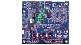
So, I then resorted to your trick of cutting the tracks. First I cut the one labelled '1' with a red arrow. The resistance to ground remained unchanged (57 Ohms). Next I cut the one labelled '2' with a green arrow. Finally that had an effect in that the resistance to ground from the regulator output is very high
I think this means the problem is with the CS4398 so it's new DAC time?
Thanks,
Andy.
Thank you for your suggestions. I've removed all of the resistors that I think are downstream of the regulator but to no avail (including those circled in the attached pic).
So, I then resorted to your trick of cutting the tracks. First I cut the one labelled '1' with a red arrow. The resistance to ground remained unchanged (57 Ohms). Next I cut the one labelled '2' with a green arrow. Finally that had an effect in that the resistance to ground from the regulator output is very high
I think this means the problem is with the CS4398 so it's new DAC time?
Thanks,
Andy.
Attachments
Hello,
it seems that your CS4398 is fried indeed Well, if you have a closer look at the full schematic of this DAC, you will notice that the circuit itself is not that complicated and the only component which could fail are either capacitors ( they might blow up ), resistors ( burn and cannot be measured again ) or the ICs ( voltage regulators, decoders etc. ).
Ok, in theory you could replace the CS4398 with a new chip if you have the tools to desolder the chip. You could eg. request a new CS4398 chip for free from Cirrus Logic, as an engineering sample.
But maybe buying a new ( empty ) PCB and using new components might be the better deal.
Best regards,
it seems that your CS4398 is fried indeed
Well, if you have a closer look at the full schematic of this DAC, you will notice that the circuit itself is not that complicated and the only component which could fail are either capacitors ( they might blow up ), resistors ( burn and cannot be measured again ) or the ICs ( voltage regulators, decoders etc. ).Ok, in theory you could replace the CS4398 with a new chip if you have the tools to desolder the chip. You could eg. request a new CS4398 chip for free from Cirrus Logic, as an engineering sample.
But maybe buying a new ( empty ) PCB and using new components might be the better deal.
Best regards,
Dear Gorgomat, you are not alone, at list we are in two!
I already assemble one original board and now I'm waiting for a unpopolated one to apply this tread power sopply mod.
Also I'm working on an idea to apply some modification i found here on diyaudio forum on a similar board.
I'm curious to see your work.
I already assemble one original board and now I'm waiting for a unpopolated one to apply this tread power sopply mod.
Also I'm working on an idea to apply some modification i found here on diyaudio forum on a similar board.
I'm curious to see your work.
I can confirm that my modified PSU works very well with the enhanced capacitor values ( 4700µF instead of the 2200µF, 2x 1000µF instead of 2x 220µF etc. )
I also added 2x 1200 Ohm resistors ( one parallel connected to each 1000µF capacitor ) to make sure that the current draw of the 7x12 regulators is high enough to prevent oscillations.
The tricky part will be to change the output buffer in order to match the suggestion of the CS4398 datasheet:
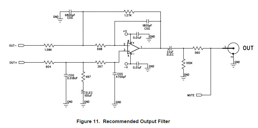
Since my DIY valve amplifiers I use already have input capacitors, I can easily skip the 22µF capacitor + 100k Ohm resistor + 560 Ohm resistor.
I´m not quite sure how I will improve the board and this one is really crowded by now...but what is 100% positive is that I will have to drill some extra holes for the extra components and also scratch some of the connections in order to solder them.
One thing is for sure, the modified board will look really ugly but hopefully sound even better
Best regards,
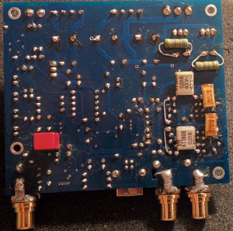
I did it I managed somehow to build the recommended stage but I had many problems. I skipped the 22µF capacitor + 100k Ohm resistor + 560 Ohm resistor.
Some resistor values cannot be purchased in Germany, I had to chose the next closest value. Same goes for the capacitors, I could not get the desired values...I used old stuff I had laying around and the PCB looks like a mess. The capacitors are really old but "NOS"...but I would have prefered some Wima capacitors.
While I realised that I will have to solder more stuff below the PCB, I also changed the 10nF capacitors with huge 10nF Wima FKP2 I had laying around
Instead of using 1,8nF capacitors, I had to use 2x 1nF in parallel ( 1 soldered below the PCB ).
Be warned that this PCB is super sensitive once you´ve attached the first components. I managed to break some connections and had to fix them with wires... Be careful if you own a super strong solder pump too...it might rip away your connections. Better use desolder wire instead.
This board looks really ugly the way I attached the components but from a electrical point of view, it works.
Here are 2 pictures :
I like the sound of it but to be honest, I´m not sure if it sounds worse or better. I won´t touch the PCB again
Best regards,
I managed somehow to build the recommended stage but I had many problems. I skipped the 22µF capacitor + 100k Ohm resistor + 560 Ohm resistor.Some resistor values cannot be purchased in Germany, I had to chose the next closest value. Same goes for the capacitors, I could not get the desired values...I used old stuff I had laying around and the PCB looks like a mess. The capacitors are really old but "NOS"...but I would have prefered some Wima capacitors.
While I realised that I will have to solder more stuff below the PCB, I also changed the 10nF capacitors with huge 10nF Wima FKP2 I had laying around
Instead of using 1,8nF capacitors, I had to use 2x 1nF in parallel ( 1 soldered below the PCB ).
Be warned that this PCB is super sensitive once you´ve attached the first components. I managed to break some connections and had to fix them with wires... Be careful if you own a super strong solder pump too...it might rip away your connections. Better use desolder wire instead.
This board looks really ugly the way I attached the components but from a electrical point of view, it works.
Here are 2 pictures :


I like the sound of it but to be honest, I´m not sure if it sounds worse or better. I won´t touch the PCB again
Best regards,
Last edited:
Congrats Gorgomat.
I think I will approach building the output stage differently, by building it on a separate board. This way I do not have to install any of those parts on the bare (ICs soldered) PCB that I ordered.
I also plan to omit/bypass both the CM102 and CS4016 and tap directly into the i2s inputs of the CS4398. The i2s pins break out nicely to some resistors (which normally go to the i2s output of the CS4016) so it should be quite easy to make i2s headers there.
I am also considering bypassing the onboard power section by building my own regulators, but maybe the trick you mentioned with the 1200ohm resistors is enough to clean up the power. We'll see.
Still waiting for the board.
Last edited:
- Home
- Source & Line
- Digital Line Level
- DAC: CS4398 with CS8416+CM102s