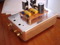
Nice build Stixx. I would have placed the transformer away from the outputs though. Despite the shielded cable it would have been better to avoid 50 Hz stray-in at all. Maybe you can use a "mumetall" sheet. I use that often and it results in total shielding. I would place the transformer to the front side of the case, move the DAC PCB closer to the RCA outputs and the shunt supply somewhat to the right (so the transformer and the shunt supply 180 degrees turned).
Thanks JP. My idea was to place the transformer close to the IEC inlet to have the AC wiring as short as possible. I also tried to have all the connections as short as possible, and I'm not sure whether I met that goal
")
Anyway the hint with the Mu-metal is a good one... do you have a source you can disclose?
Mu Metal miniature shielded cans of a quality that you would be happy with
the mumetal and/or annealing is an option mentioned in the PDF download, I plan to grab one of these for an internal shockmounted clock module for my dac at some point. i've often drooled over their cool as hell flight cases and rack cases too; in particular the Zerak, Scout and Val-An 700
at one stage I was thinking of building my dac and amp directly into one
Last edited:

no worries =) i'm actually keen to see what you do with it. they have 5 axis laser cutting too for mods, though I'm a bit scared how much that would cost looking at their client list.
the thing with mu-metal is you cant machine it without screwing with the metallic grain and thus permeability, they have standard options with mounting facilities and hundreds of shapes so probably you could work it out. I feel certain theyve made transformer cans before, however maybe it would be even better to shield the dac.. make sure to update the thread =)
the thing with mu-metal is you cant machine it without screwing with the metallic grain and thus permeability, they have standard options with mounting facilities and hundreds of shapes so probably you could work it out. I feel certain theyve made transformer cans before, however maybe it would be even better to shield the dac.. make sure to update the thread =)
yes I think soLOL, these cans must cost more than my whole el cheapo build
Same combo, SSLV1.1 Bib on a perforate board + JP/Subbu v2.6 except it is a surplus 3 for $10 alu can
but if youve seen Stixx's headamp builds you'll know he likes a nice clean enclosure and likely spends more on that than the innards on most occasions =) so I didnt hesitate.am I right, did you actually UN-twist ethernet cable for your output wiring? original hehe.
love the regulator lovechild dry humping the dac enclosure =)
Last edited:
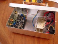
pchw, your placement of parts is better but output wiring could be shorter by omitting the output connector and solder solid wire first in the DAC PCB and then to the output connectors. Minor detail.
Me too. I suspect the LM723 power supply PCB will fit in the enclosure which will be at least visually somewhat more appealing.
love the regulator lovechild dry humping the dac enclosure =)
Me too. I suspect the LM723 power supply PCB will fit in the enclosure which will be at least visually somewhat more appealing.
Last edited:
Thanks JP. My idea was to place the transformer close to the IEC inlet to have the AC wiring as short as possible. I also tried to have all the connections as short as possible, and I'm not sure whether I met that goal
Anyway the hint with the Mu-metal is a good one... do you have a source you can disclose?
Better longer AC wiring than 50 Hz stray-in from the transformer...
I use NOS mumetal sheets but stock is almost gone. Can't remember where I got it from, it was a long time ago.
Qusp, yup, all safety green, approximately 1/2 - 2/3 of a 1K meter roll.
JP, the way that it is set up is to provide flexibility for testing the 2nd v2.6 board soon. At the moment, I can swap any parts inside at ease. Judging from Subbu's completed PS board in the picture, I probably can fit it inside with very minimal effort.
The woman doesn't care the look of my toys; therefore, I would rather spend for more toys than only a few pretty toys Seriously, that's the beauty of this hobby, do what makes yourself happy!!
JP, the way that it is set up is to provide flexibility for testing the 2nd v2.6 board soon. At the moment, I can swap any parts inside at ease. Judging from Subbu's completed PS board in the picture, I probably can fit it inside with very minimal effort.
The woman doesn't care the look of my toys; therefore, I would rather spend for more toys than only a few pretty toys
Seriously, that's the beauty of this hobby, do what makes yourself happy!!Dang, yes...but if youve seen Stixx's headamp builds you'll know he likes a nice clean enclosure and likely spends more on that than the innards on most occasions =)
Have finnished one DAC pcb and tried it,but at the 3,6v regulator (U3) there was 1,75v out so I desoldered L4 and..now theres 0v out from the reg,and on the DAC chip pin 5 theres 1,75v,even with U3 desoldered,how can that be?
Is it from the oschillator voltage?
Anyhow does anyone have a couple of 3,6v regulators to sell to me??
Is it from the oschillator voltage?
Anyhow does anyone have a couple of 3,6v regulators to sell to me??
Åke, can you post some closeup photos?
L4 is a fairly robust part that should not cause any problems. It can handle 1.5A, it's passive and it tolerates heat reasonably well.
You can test with 3.3V regulators at U3. The ES9023 can be run on 3.3V and 3.6V. 3.6V is preferred because it gives 2V out and solves some other issues along the way also.
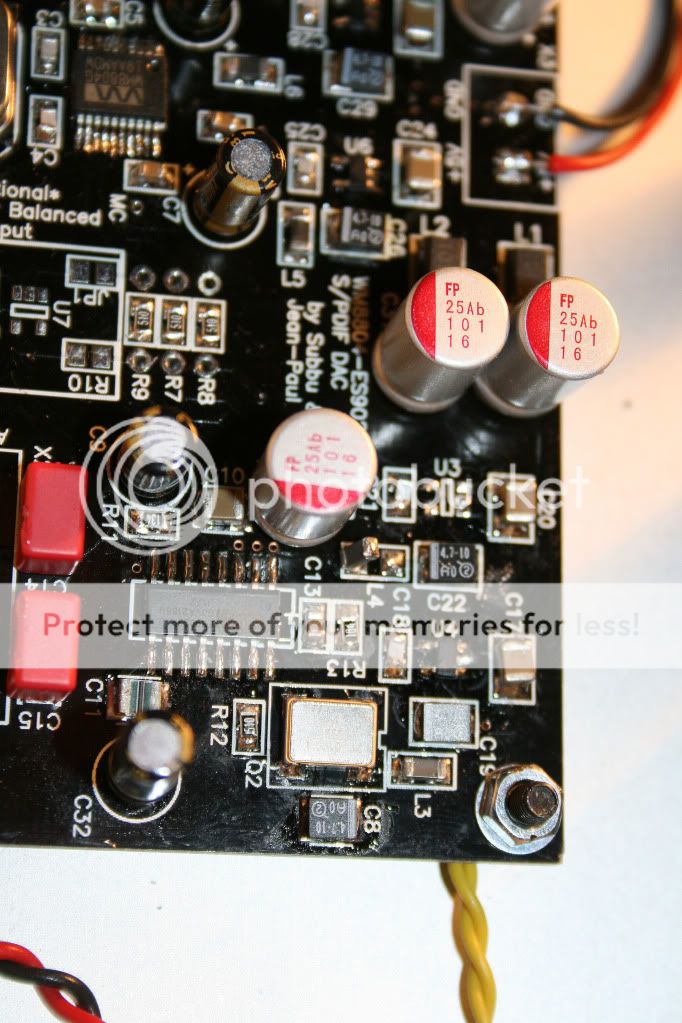
Please replace the reg and clean the PCB with cotton swabs and isopropyl alcohol 99%. Then test. I would replace the ES9023 as well just to be sure but that's a personal choice. I just don't like to replace parts twice with the modern PCB materials....
*Always work ESD safe when working with CMOS chips*
*Always work ESD safe when working with CMOS chips*
Last edited:
- Status
- This old topic is closed. If you want to reopen this topic, contact a moderator using the "Report Post" button.
- Home
- Source & Line
- Digital Line Level
- ES9023 DAC PCB