Yep. And that statement doesn't ealign with the group delays given on page 11---typical equiripple, linear phase synthesis produces group delays four or five times larger. My best guess is "linear phase" in this context refers to the usual minimum phase synthesis with constraints to keep phase shifts below subjectively audible levels. Alternatively, the filters really are linear phase and Cirrus found some pretty nice optimizations to bring the group delay down into the range more typically associated with minimum phase filters.The Cirrus part you quoted explicitly says its linear phase - p74, para 8.2 of the datasheet.
Either case is a nice proposition on paper. The reason my guess is the former is that if one looks across Cirrus's product line their higher end parts (-100dB THD / 110dB DNR or better) all seem to use similar filters. In particular, the CS4365 eval boad datasheet provides impulse responses in figures 12, 23, 26, 27, 40, and 41. These are intermediate phase but not strongly so at double and quad speed---one can split hairs over exactly how much preringing can exist in a minimum phase response versus an intermediate phase one but it's not unreasonable to characterize those 4365 responses as minimum phase and the group delays on the 42526 are lower. Next step would be to get a board together and measure the part's impulse response to confirm or deny. You're right that I should have said lower group delay rather than calling out a particular type of impulse response.
I suppose I should note the single speed fast rolloff on the CS42526 looks more like intermediate phase to me---my filter optimization tools leave quite a bit to be desired but, having poking around in the space, my guess would be the phase targets couldn't be hit in minimum phase with the available taps.
If you examine the freq response plots (fig 46ff) then its clear these aren't equiripple designs as the passband ripple error is bigger (at 0.008dB by eye from the graph, or 0.035dB from the table) than the stop-band (0.0003dB). Judging by the impulse response plots on the eval board you mention, the 2fs response looks min-phase but the 1fs-2fs interpolator isn't. So my guess is its a multi-stage implementation where the stages after the 1st are min-phase. How they manage to get the 0.0uS group delay variation with freq then is beyond me. I agree though that the 12 sample group delay looks inordinately low, but then again the transition width is a tad wider than normal (4.8kHz vs 4.1kHz for the usual half-band offerings)
An Android solution basing on the CM6206 USB-audio chip ?
To get you started you need to know what's ALSA (Android Audio System).
Android Audio System(2): ALSA Layer - Thinking beyond Source Code
CM6206 is supported by ALSA, thanks to Wolfgang Breyha and Takashi Iwai.
sound/usb/format.c
revision 8129e79ed7932bd11d60518d62434a0b687e5771
CM6206 datasheet is available here : CM6206 datasheet
Go in the middle of the webpage : Datasheet Download, CM6206, Click to view pdf file
Attachments
Last edited:
I suspect there's some rounding down in the ADC spec.How they manage to get the 0.0us group delay variation with freq then is beyond me.
") The group delay variations for the DACs are more believable, particularly as the range over which the variation is taken are clearly stated.
The group delay variations for the DACs are more believable, particularly as the range over which the variation is taken are clearly stated.I've not found any papers from Cirrus discussing their filter design methodology but use of genetic algorithms to evolve a more optimal filter is common. Also, various fast variants of bit flipping exist which attempt to find the optimum among all possible coefficient values (Wolfson mentions using such approaches in this paper). Cirrus likely employs similar numerical methods so it's possible they hit the jackpot on the ADCs. However, I'll need to measure 0.0us to believe it---if the filter's really that good I'd expect to see it on the DACs as well.
I suspect there's some rounding down in the ADC spec.
Ah thanks for pointing that out - I was reading the wrong page and attributed the ADC parameters to the DAC, duh!
Looking over the correct page now what puzzles me is that these characteristics (-3dB @ 0.5fs, symmetry of pass and stop bands around 0.5fs) shout 'half-band filter' at me. But I was under the impression that half-band filters were only good for linear phase? Isn't the half band saving arising from the symmetry of the impulse response in the time domain? If so then the DAC group delay variations must be arising in the analog part.
A proper firmware would not operate with a 48 kHz interrupt. Very, very few, if any, are organized that way. The proper method is to use DMA to move desired input and output audio data samples between memory and converter I/O. Then, an interrupt occurs once per buffer instead of once per sample, and the processor bounces between a pair of ping-pong buffers (per channel) so that processing can occur on one data set while the other is being shuttled to and from the converters or other data link (I2S).The above figures are only valid in a "bare metal" programming style structured as a main_loop (where all the background tasks get explicitely scanned) plus a proper 48 kHz interrupt (context save, all the audio DSP on a sample-by-sample basis, context restore). Adding a SPI communication for sending control data to the Codec will cause an extra interrupt, to be carefully managed for not interfering with the 48 kHz interrupt. A possibility is to manage such SPI, not using a hardware SPI, but using a software SPI (bit-banging) operating at 48 kHz, programmed within the audio DSP interrupt.
Some of your points were valid, though, such as the fact that a high-level OS will needlessly waste CPU cycles and reduce your total capabilities, and also that every added feature takes away from CPU cycles for audio processing. However, with proper DMA support and interrupt priorities, it becomes very easy to manage a lot of simultaneous tasks without a multitasking operating system.
You just have to hope that the various DMA and other peripherals do not have bugs which only occur when they're all running at full speed. I've certainly found such bugs in chips when I had a lot going on (e.g., 6 million samples per second, 16,000 7-stage FFT operations per second, 775 kbps over Full Speed USB), and the manufacturer of the chip was not even aware of the limitations. Fortunately, juggling tasks around from one resource to another solved the problem.
By the way, if anyone knows of a professionally-designed DSP product that has an interrupt per audio sample, please let me know. That would be a very interesting design choice considering the number of cycles of overhead per interrupt.
Long time ago, in the early days of audio DSP, when the Motorola DSP56K was king, all professional systems were designed using one interrupt per audio sample (stereo sample). In order to completely avoid the context save/restore, Motorola allowed a "fast interrupt" modality (code consisting of ony two words), very effective when the only duty of such fast interrupt was to put (or read) the audio data in a (very short) buffer using a hardware-driven circular pointer. For the application, it was mandatory to keep the latency as short as possible. The buffer thus needed to be as short as possible, say 2 samples : the stable sample being processed, and the new sample possibly incoming. Would you need a larger buffer, your customer would get the impression that you were lazy and messing with the signal flow. Back in those times, the 14-bit DACs had no latency time, not being Sigma-Delta. Same for the ADCs, needing multiturn trimmers and periodic calibrations. It was essential to have no delay between the touch of a button, and the acoustic response. Think about a digital piano that you play realtime, with your fingers. Think about a very responsive digital mixing & recording desk, operated by your fingers during a performance in a concert hall, featuring the same reaction time as an analog desk. Back in those times we were very happy with the DSP56K, only regretting that Motorola had not added a shadow register set, a feature seen on the Intel 8051 (four banks) and also seen on the 32-bit MIPS (one shadow register set). With the DSP56K, we were quite happy with the hardware-driven circular buffer. Today in 2012, you are asking "if anyone knows of a professionally-designed DSP product that has an interrupt per audio sample". I hope you've got an intelligible answer. There is no free lunch. If you target a professional look and feel without time lag, on a bloated machine like Linux "where everything is a file" or Windows "where everything is abstraction", yes indeed you'll need a 3 GHz quadcore CPU and a buffer as short as possible, say 8 samples. That's the lazy way. And you'll still suffer from latencies, because of the Sigma-Delta ADCs and DACs. If you target a professional look and feel without time lag on a Cortex-M4 clocked at 100 MHz or so, you need to apply bare metal programming (avoid files and abstraction layers), need to apply DMA (no fast interrupt scheme available), and need to keep the signal flow very tight (use pointers instead of physical transfers). If your hardware is slightly underpowered, you may end up using buffers (say eight samples), as a last resource, for dividing by eight the impact (the overall oherhead) of the context save/restore. Nowadays, there are many so-called "professional" stickers appearing on audio gear, that are toys and/or jokes. Here is not a joke : have you seen what modern technology allows in 2012, in a real professional environment like DSL (cable modems) ? A modern DSL DAC like the MAX5891 is a non-oversampling 16-bit DAC, 600 Msps, producing no glitches and no time lag. Get some 24bit/96kHz audio material, oversample it by a factor of 256 and feed the resulting 16-bit data to the DAC at 24.576 MHz using LVDS. Fit a passive 1st-order lowpass at the DAC output. Design the power amp as a 2nd-order lowpass, in such a way that the combined transfer function is a 3rd-order Bessel lowpass -3dB at 50 kHz. This is the kind of DAC that Herbert Von Karayan would only dare to listen at home, if he was still alive. Unfortunately, that kind of "professional audio" doesn't exist anymore. Actually, he would have concluded that the same approach is needed at the ADC side, with the combined ADC and DAC analog filters, materializing a 6th-order Bessel lowpass. No time lag. No more than 2 samples as buffer. Per device, or in the whole chain ? Such was the pro-audio philosophy, long time ago, before the cheap and easy 2496 era. Interested now ?By the way, if anyone knows of a professionally-designed DSP product that has an interrupt per audio sample, please let me know. That would be a very interesting design choice considering the number of cycles of overhead per interrupt.
Thank you for the perspective, Steph.
At first I thought we might be getting off-topic, but I think that everything you mentioned is an important consideration for a DSP crossover.
My first attempts at DSP were on the 56K. Unfortunately, my development platform, the NeXT computer, was not always cooperative. I do remember the days when all DAC and ADC chips had no latency from internal digital filters. I believe, though, that there has never been a 24-bit converter without such latency. Thus, you have to make a choice between 24-bit support or 0 latency.
The 6 million samples per second design that I mentioned above is implemented with a 14-bit DAC capable of 125 MHz sample rate and no latency (my hardware adds a sample of latency to reduce parts counts). Also, I confirmed that interrupt routines written in the C language have far more cycles of overhead than interrupt routines written in DSP assembly, at least with the TMS320 family, and thus my product uses assembly for all interrupts. The C language is convenient for the bulk of the flow in the firmware, but there's no sense wasting cycles if it can be avoided via better programming.
Your 600 Msps 16-bit DAC could potentially be used in an excellent DSP XO. With 16 bits per driver, over multiple frequency bands, there might not be such need for 24-bit performance. The typical listening environment requires no more than 18 or 19 bits of quantization on playback anyway, so a three-way speaker system with 16 bits per speaker driver might actually be sufficient.
From another perspective, though, playback is less demanding than piano synthesis or live mixing. A few samples of latency in a DSP XO would be no different than a slight repositioning of the speaker cabinets, and can even be compensated away for prerecorded music.
I'm almost sorry that I challenged you about the interrupt-per-sample design. You clearly know what you're talking about. I was speaking from viewpoint of modern designs with modern DSP chips (although I still consider the 56K to be a valid choice). I have certainly considered designing systems with only a single sample of latency, and I believe that some products in earlier decades worked this way, but I have never had conclusive information about specific products. As for modern products, my queries have resulted in learning that even the best DSP systems today have some number of samples of latency, even if only 16 or 32. The good news here is that the group delay of an EQ plugin can often be compensated by absorbing it into the required latency of the overall system. In other words, the built-in latency allows multiple parallel audio paths to be time-aligned without further latency. Unfortunately, any DAC latency cannot be avoided.
No need to be sorry, your stimulus made me remember a couple of enjoyable things. Thanks.Thank you for the perspective, Steph. I'm almost sorry that I challenged you about the interrupt-per-sample design.
An l-th band Nyquist filter has the properties of having every l-th coefficient as zero and a cutoff of 0.5Fs. Half band filters are the special case of a second-band Nyquist with a symmetric impulse response. Symmetry means some die area can be saved in coefficient storage but the primary advantage of a second-band filter is the multiply by zero and add can be skipped, reducing computational cost by half compared to a filter with the same number of taps and all coefficients nonzero.Isn't the half band saving arising from the symmetry of the impulse response in the time domain?
Nyquist filters can also be minimum phase. I don't know enough about their synthesis to speculate about the number of stages Cirrus might be using or whether their parts' responses look like second-band, third-band, etc. Nyquist filters. If I get the time I might fool with some basic minimum phase synthesis and some stages that fit into the 128/64/32x single/double/quad oversampling Cirrus tends to use.
Last edited:
Right ! You may store a few soundtracks on the SDCARD, and ask the LPC4330-Xplorer to process them realtime in digital domain. This way you can demo the stereo 4-channel crossover without needing an external audio source.
Speaking about 8-channel audio demos, you can generate multichannel dynamic sound effects like smoothly "moving" the sound from one output to the other, surprising the audience, attracting the audience. You may embed this into public transportation systems, shop & bar entrances, exhibition booths, vending machines, casino machines.
Don't worry about the audio DSP capabilities of the LPC4330. Say the Cortex-M0 is entirely busy servicing the Serial GPIO. The Cortex-M4 remains thus available for general housekeeping and audio DSP. Say the audio DSP job represents 75% of the Cortex-M4 workload. Say there are 12 Cortex-M4 instructions needed for executing a BiQuad IIR. Say the CPU clock is 100 MHz. Say the audio sampling frequency is 48 kHz. You thus can execute 130 BiQuad IIRs. Say there are 8 audio channels. Each audio channel can thus get processed by 16 IIR BiQuads in series.
There is one area where the LPC4330-Xplorer board may be lagging : RAM capacity. In this particular case, plugging a SDCARD into the system, you can use it as slow RAM, operating at the audio sampling frequency. If, for example, you need to introduce delays in the audio rendering, you would read the audio soundtrack in the SDCARD, using eight different pointers. This way you get all the time shifts you want.
i would prefer a dedicated DSP with more-than-enough number cruching capability and sufficient (expandable) memory for this kind of task. after implementing DSP XO, we may look forward for some equalization too.
have anybody taken look at this? this one costs USD150.
Symphony™ SoundBite - Affordable Audio DSP Development Kit Product Summary Page
Last edited:
Indeed, and I own such one, still unopened on my shelf. The DSP56K looks like a valid choice untill you face two details. Have you tried buying a DSP56371 (like in the Freescale Symphony SoundBite kit) or a DSP56374 (like in the Elektor DSP platform by Alexander Potchinkov) ? Guess what : all single core DSP56K chips are now listed by Freescale as "not recommended for new designs". The second detail is the 24-bit resolution. My little IIR_Lab application shows that you should not program a Linkwitz Transform with such resolution. An additive/substractive Parametric Equalizer may be more robust. MiniDSP opted for the SigmaDSP ADAU1701 from Analog Devices, featuring a 28-bit signal path and a 56-bit MACC result. When you are talking about equalization, how many IIR BiQuads are you targeting ? Ten IIR BiQuads per stereo channel ? Thus, twenty IIR BiQuads ? A LPC4330 will do this, on top of the crossover job. Do you need two more IIR BiQuads per speaker driver, for better linearizing their Bode Plot before applying the crossover functions ? Say there are eight speaker drivers in total : it makes sixteen more IIR BiQuad in total. A LPC4330, running close to 200 MHz, will do this, using a 32-bit resolution.I would prefer a dedicated DSP with more-than-enough number cruching capability and sufficient (expandable) memory for this kind of task. After implementing DSP XO, we may look forward for some equalization too. Have anybody taken look at this? this one costs USD150.
Symphony™ SoundBite - Affordable Audio DSP Development Kit Product Summary Page
If you intend applying 256-tap FIRs as crossover filters, as speaker driver equalizers, and as global equalizers, you need a more powerful DSP operating in the near GHz range like a T.I. Sitara AM3358.
You may try deconvolving the listening room with, say, a 33ms-long FIR containing 3,168 samples at 96 kHz, hence about 600 MACC per second in stereo. You thus need a second T.I. Sitara AM3358.
Of course without the Linux/Android bloat. You need a bare metal programming style.
BeagleBone, quite inexpensive, hosts a T.I. Sitara AM3358. Up to you to configure the McASP for outputting the required I2S lines on the BeagleBoard header connectors.
http://beagleboard.org/bone
Read this : http://e2e.ti.com/support/dsp/sitara_arm174_microprocessors/f/791/t/182692.aspx
Last edited:
I don't understand your complaint. The "24-bit" DSP56K has the same 56-bit MACC result. The 28-bit signal path might prove an advantage, but both processors have the same size 56-bit accumulator registers.... The second detail is the 24-bit resolution. My little IIR_Lab application shows that you should not program a Linkwitz Transform with such resolution. An additive/substractive Parametric Equalizer may be more robust. MiniDSP opted for the SigmaDSP ADAU1701 from Analog Devices, featuring a 28-bit signal path and a 56-bit MACC result.
I believe his point is 24-bits isn't enough in the signal path. 28-bits is better but why not go for 32 with the Cortex M4? See also the link in the first post of this thread - here's an abstract:
This data should dispel once and for all the myth that digital filters aren't noisy. With 'only' 24 bits of signal processing, the Direct Form filter is inferior to the analog filter at frequencies below around 300 Hz. At a 10 Hz cutoff frequency, the digital filter's noise level is worse by 34 dB than the analog filter.
This data should dispel once and for all the myth that digital filters aren't noisy. With 'only' 24 bits of signal processing, the Direct Form filter is inferior to the analog filter at frequencies below around 300 Hz. At a 10 Hz cutoff frequency, the digital filter's noise level is worse by 34 dB than the analog filter.
Indeed, and I own such one, still unopened on my shelf. The DSP56K looks like a valid choice untill you face two details. Have you tried buying a DSP56371 (like in the Freescale Symphony SoundBite kit) or a DSP56374 (like in the Elektor DSP platform by Alexander Potchinkov) ? Guess what : all single core DSP56K chips are now listed by Freescale as "not recommended for new designs". The second detail is the 24-bit resolution. My little IIR_Lab application shows that you should not program a Linkwitz Transform with such resolution. An additive/substractive Parametric Equalizer may be more robust. MiniDSP opted for the SigmaDSP ADAU1701 from Analog Devices, featuring a 28-bit signal path and a 56-bit MACC result. When you are talking about equalization, how many IIR BiQuads are you targeting ? Ten IIR BiQuads per stereo channel ? Thus, twenty IIR BiQuads ? A LPC4330 will do this, on top of the crossover job. Do you need two more IIR BiQuads per speaker driver, for better linearizing their Bode Plot before applying the crossover functions ? Say there are eight speaker drivers in total : it makes sixteen more IIR BiQuad in total. A LPC4330, running close to 200 MHz, will do this, using a 32-bit resolution.
If you intend applying 256-tap FIRs as crossover filters, as speaker driver equalizers, and as global equalizers, you need a more powerful DSP operating in the near GHz range like a T.I. Sitara AM3358.
You may try deconvolving the listening room with, say, a 33ms-long FIR containing 3,168 samples at 96 kHz, hence about 600 MACC per second in stereo. You thus need a second T.I. Sitara AM3358.
Of course without the Linux/Android bloat. You need a bare metal programming style.
BeagleBone, quite inexpensive, hosts a T.I. Sitara AM3358. Up to you to configure the McASP for outputting the required I2S lines on the BeagleBoard header connectors.
BeagleBoard.org - bone
Read this : Configuring McASP for the AM3358 using Starterware (Beaglebone) - AM335x Cortex-A8 Microprocessors Forum - Sitara? ARM® Microprocessors - E2E
i am not from DSP background. if you have confidence that LPC4330 has enough capacity to perform all the required DSP calculations then lets go ahead with this.
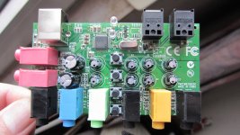
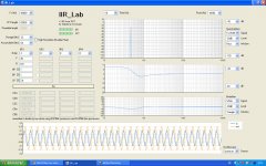
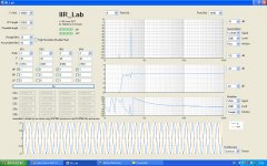
I've asked IIR_Lab to graph the results on a Linkwitz Transform. Clearly, the 24-bit data 56-bit acc delivers more noise and distorsion than the 28-bit data 56-bit acc.I don't understand your complaint. The "24-bit" DSP56K has the same 56-bit MACC result. The 28-bit signal path might prove an advantage, but both processors have the same size 56-bit accumulator registers.
Attachments


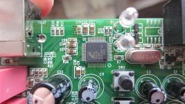
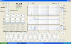
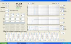
Same pattern for a 30 Hz Butterworth 8th-order Highpass (Fs = 96 kHz).
Attachments
Well you don't need to stick to direct form...
There's a whole lot of alternatives available and very well documented: double precision, error feedback, state-space etc.
Also this 300 Hz your quote refers to is suspicious. Is there a context that goes with the quote?
Finally, 24 bits is 144 dB of dynamic range: that covers everything from ants walking to the heart of the space shuttle's engines. If you can't do proper audio processing on a 24-bit platform then maybe you should indeed stick to analogue filters and let dsp to dsp guys. This doesn't mean that Cortex is not suitable - just don't say that 24 bits are not enough because that's false information.
I believe his point is 24-bits isn't enough in the signal path. 28-bits is better but why not go for 32 with the Cortex M4? See also the link in the first post of this thread - here's an abstract:
This data should dispel once and for all the myth that digital filters aren't noisy. With 'only' 24 bits of signal processing, the Direct Form filter is inferior to the analog filter at frequencies below around 300 Hz. At a 10 Hz cutoff frequency, the digital filter's noise level is worse by 34 dB than the analog filter.
I agree. There are textbooks which show multiple different implementations of the same digital filter, and graph the different frequency precisions available in each. If 300 Hz or 10 Hz is working poorly with your implementation, then you need to change the code. There might not be a single piece of code that can sweep a single cutoff parameter from 10 Hz to 40 kHz, but that's generally not needed in a crossover. You have plenty of opportunity to optimize your filter for low frequency or high frequency or whatever is needed.Well you don't need to stick to direct form...
There's a whole lot of alternatives available and very well documented: double precision, error feedback, state-space etc.
Finally, 24 bits is 144 dB of dynamic range: that covers everything from ants walking to the heart of the space shuttle's engines. If you can't do proper audio processing on a 24-bit platform then maybe you should indeed stick to analogue filters and let dsp to dsp guys. This doesn't mean that Cortex is not suitable - just don't say that 24 bits are not enough because that's false information.
Interesting discussion. Let's focus on a Butterworth highpass 8th-order 30 Hz -3dB. Sampling frequency 96 kHz. What method would you advise, on a DSP56K, for getting rid of the noise & distorsion produced by the native (naïve ?) series IIR BiQuad implementation ? Keep in mind we need the exact same Bode plot. What would be most exact and efficient way ?
- Boosting the precision using more elaborate arithmetic routines for the multiply-accumulation (say, reaching a 32-bit data path inside the BiQuad, operating with 64-bit accumulator) ? What would be the computing time penalty ?
- Decimating the signal, applying a series IIR BiQuad in a lower sampling frequency context, upsampling the signal for getting back a 96 kHz sampling frequency ? What decimation factor to use ? Can we guarantee a Bode plot that's exact ?
- Any other method welcome
- Status
- This old topic is closed. If you want to reopen this topic, contact a moderator using the "Report Post" button.
- Home
- Source & Line
- Digital Line Level
- Open Source DSP XOs