For audio enthusiasts like we have on diyAudio, the silicon that we need is the digital engine sitting in the SWEEX SC016 silicon (thus, without ADCs and DACs), upgraded to 24bit/96kHz. No doubt it will come in due time, inexpensive, as this is a mass market.
One may consider a group buy if such silicon remains ignored by Digi-Key, Mouser and Farnell.
In the meantime we may try hooking the SWEEX SC016 on CuBox or Raspberry Pi.
Later on we'll base on this experience for hooking the SWEEX SC016 on a Android 4.0 device.
A purely software affair, thus !
The CuBox and Raspberry Pi solutions are no short-term solution. They are suited to active speakers, embedded into active speakers. Cost remains low because of no graphical user interface..
The Android 4.0 solution would provide a high quality user interface, easing the setup. Especially using a 10 inch tablet and a physical keyboard, as development system for the XOver.
Once the Android 4.0 solution is completed, there would be a way to migrate it on CuBox and Raspberry Pi.
Cmedia CM6620 is a USB2.0 high-speed audio processor that can support the latest USB Audio Device Class Definition V2.0 and 7.1-channel true high-definition audio and Line-In/Mic-In (all up to 192KHz/24bit). The problem with the CM6620 is that it provides an HDA link (Intel High Definition Audio) instead of four I2S lanes or one TDM.
The VIA VT1730 is an USB 2.0 (480 Mb/s) 8-channel, 24-bit/192 kHz audio controller specifically designed to achieve cinema-quality audio recording and playback in high fidelity USB applications. The highly integrated single chip USB audio solution is embedded with a number of crucial modules, including a standard 8032 MCU core, USB transceiver, five I2C masters and one slave controller, an I2S controller, a serial flash controller, four SPI ports, phase locked loop (PLLs) with internal oscillator, and a 3.3 V~2.0V regulator. The VIA VT1730 supports multi-channel PCM digital audio format up to 24-bit resolution and 192 kHz sample rate. An S/PDIF interface with two stereo output ports and one stereo input port supports up to a 24-bit resolution and 192 kHz sample rate.
Are there other USB 2.0 audio controllers nowadays, outputting four I2S lanes or one TDM ? Equipped with a S/PDIF input ?
Are there people writing Android 4.0 drivers for USB 2.0 audio controllers ?
This is what we are looking for. Forget about the five I2C masters.VIA VT1730 .... an I2S controller
Last edited:
So, what about hardware?
Should we really stick to PC+USB thing? PC+PCI are easily obtainable, with 4 I2S outputs, slaving ability etc, so if we are going with PC, why not? There is no logical difference between USB and PCI - PC is always there.
And if we are going for less than 100% best DACs - then PCI multichannel cards are fine for us...
Yet, PC thing is bad - that's why we want stand-alone hardware DSP.
If we won't target the CPU-hungry FIRs (and we won't - with available cheap-end CPUs and DSPs), we are goind with IIRs.
Why do we need DSP for? Do we want to change presets every day/week? I guess so, till we find the right preset, and leave it for a while...
We need it to be hardware, perfect SQ, and active. Why won't we just stick to analog circuits? These are cheap, somewhat better quality than DSPs (no bits truncations etc), yet painfull to modify. Digital IIRs mimic the analog circuits anyway...
How about PC based crossover to find the right filers, and then build these filters in analog-hardware? It's cheap way (nice sounding soundcards with 8ch outputs are already there and not that pricey, analog boards are opamp price dependant), flexible as your PC software could be, and as long as your digital filter's transfer functions match these in analog cookbooks, you can transfer digital domain filters to analog hardware.
Software which will do the PC-based sim, and calculate the parts for analog circuits? I already have a program that generates biquads and transfers them to foobar plugin, which passes the sound thru my biquad chains and plays thru multichannel soundcard. Everything is in real time.
Analog circuits sim is already there, but i had issues with modeling the analog transfer functions in the digital domain (analog TF to biquads). I guess i should put bode plots of analog and digital filters next to each other, check whether they match, and say hooray if they do. Same bode plots = same transfer functions = same sound.
Done this already using a WinXP PC executing SynthMaker, connecting on the SWEEX SC016 8-channel DAC. Using RBJ-cookbook filters (IIR BiQuads).How about PC based crossover to find the right filers, and then build these filters in analog-hardware?
Actually it is a little bit more complicated : you need VAC (Virtual Audio Cable) for telling Windows to route the audio (coming from Winamp or any other app) to ASIO, and you need ASIO4ALL for telling Windows to operate the SWEEX SC016 8-channel DAC under ASIO.
This way some time ago I started prototyping crossovers in digital domain, translating them into analog afterwards. I wrote a small Visual Basic application, easing the process. It went published in reply #12 of diyAudio post "IIR_Lab : a design help for digital audio filters" and is still available.
When you do this you realize the importance of using delay lines for properly time aligning the drivers, the woofer emission centre being usually recessed (delayed), compared to the tweeter emission centre.
Even the most straightforward 1st-order crossover needs such time alignment. Builing a crossover without paying attention to time alignment is futile !
How would you implement delays in analog ? You would cascade phase shifters, approximating a pure delay function from DC to some intermediate frequency, ideally 20 kHz. You can compensate tens of microseconds like this, using 4 or 8 opamps in the signal flow, per delay line. If you want to compensate milliseconds, you'll need far more opamps in the signal flow. A possibility is to make a tradeoff, like implementing a pure delay function, not from DC to 20 kHz, but from DC to 2 kHz or so. At the expense of phase distorsion above 2 kHz or so.
What if you want a crossover exhibiting no phase distorsion ? The usual solution is the Lipshitz-Vanderkooy (delay compensated) arrangement, not to be confused with the Linkwitz-Riley. And now guess what ? For the Lipshitz-Vanderkooy (delay compensated) arrangement, you need a delay line in the highpass elaboration, accounting for the propagation delay introduced by the lowpass section.
Crossovers thus intrinsically need delay lines (at least one for time-aligning the transducers, and one more for avoiding phase distorsion), and delay lines are unpractical using analog. The only practical way is digital, especially when wanting to avoid phase distorsion.
This being said, having already done this using a WinXP PC executing SynthMaker, connecting on the SWEEX SC016 8-channel DAC, please tell me how can I connect and program an Android 4.0 device connecting on the same SWEEX SC016 8-channel DAC. This would be my next Open Source DSP XO, if you don't mind.
You see, I'm asking myself why people keep asking about an "Open Source DSP XO", because the WinXP + SynthMaker + VAC + ASIO4ALL + SWEEX SC016 8-channel DAC is already there since years. You can trace it back since the origin in SynthMaker forum. Seems I am the only one publicly experimenting this. Nobody has publicly reported experiments using a better 8-Channel DAC. Nobody has publicly reported experiments using 24bit/96kHz natively within Winamp with audio files supplied by HDracks.
The newest SynthMaker marketing strategy doesn't help : now they disable the 8 ASIO channels on the trial version.
People don't get attracted by digital crossovers, because they know that the crossover alone, is only the emerged part of an iceberg, and can't guarantee a success.
People may welcome a total solution, a step-by-step solution, encompassing everything about multiway speaker design :
- selecting a woofer
- mesuring the T/S parameters using the added mass method
- modelling an enclosure like closed box / bass-reflex / 4th order bandpass / 8th order bandpass
- building the enclosure
- measuring the gain, phase and distorsion of the woofer in the enclosure
- measuring the polar diagram (directivity) of the woofer in the enclosure
- selecting a tweeter
- mounting the tweeter on the enclosure
- measuring the gain, phase and distorsion of the tweeter on the enclosure
- measuring the polar diagram (directivity) of the tweeter on the enclosure
- selecting a crossover topology (1st order, Linkwitz-Riley 4th-order, Lipshitz-Vanderkooy Bessel 4th-order delay compensated)
- selecting enclosure-dependent corrections like time alignment, baffle step, standing wave resonances
- selecting driver-dependent corrections like high frequency dampers, shelving
- selecting a low frequency corrections like a 2nd order Linkwitz Transform
- implementing the crossover and the corrections in digital
- connecting the power amps and the speaker drivers
- measuring the gain, phase and distorsion of the active 2-way speaker
- finely tuning the parameters
- properly documenting the finalized design, for reproduction purposes
Which means that such crossover design software needs a full-size PC (big screen, physical keyboard, mouse), for compiling the software that needs to run on some small and inexpensive crossover hardware like a few ARM Cortex-M0/M3/M4 "S/PDIF DSP+DAC bricks" designed by Richard Dudley. Or Cubox, or Raspberry Pi, or any Android 4.0 device, supplying audio data to an external USB audio peripheral (say the SWEEX SC016 8-channel DAC to begin with).
And you still have many choices about how to implement the digital filters !
You could base on IIR_Lab and program the resulting IIR BiQuads.
You could base on an analog simulation package like LTspiceIV, extract the impulse response of the filter that you want, and program it as a digital FIR (Richard Dudley).
You could enter the unfiltered gain and phase response of your driver (mounted in the enclosure), enter the desired gain response (say a 4th-order Bessel Lowpass), and a Math package like MathCad could calculate the polynomial fraction in p that you need as filter, that you would transform into a z polynomial fraction in digital, then decompose into IIR BiQuads. Or use the FIR way : graph the impulse response of the polynomial fraction in p, that you would use as FIR.
You could play the FIR card since the beginning. Amazing how some 32-tap lowpass FIRs can be selective, and phase linear. With the complementary highpass, quite selective too.
With the FIR approach, there should be a way to enter the unfiltered gain and phase response of your driver (mounted in the enclosure), enter the desired gain response (say a 4th-order Bessel Lowpass), and a Math package like MathCad or Matlab could calculate the FIR coefficients that you need as filter.
That would be the challenge.
Last edited:
Why not analogue?
Because I want to keep my source signal in the digital domain, unattenuated as long as possible
Because I can get rid of all capacitors, and I can get rid of all component degradation in the analogue components
Because I can change the eq whenever I want without having to build any circuits.
Because the title of the thread is DSP crossovers, not analogue
I can't see the advantage of the analogue circuit
Done this already using a WinXP PC executing SynthMaker, connecting on the SWEEX SC016 8-channel DAC. Using RBJ-cookbook filters (IIR BiQuads).
Actually it is a little bit more complicated : you need VAC (Virtual Audio Cable) for telling Windows to route the audio (coming from Winamp or any other app) to ASIO, and you need ASIO4ALL for telling Windows to operate the SWEEX SC016 8-channel DAC under ASIO.
As long as you need foobar-only platform, my DSP plugin and configurator program makes it easy. I've tried the SynthMaker, but found it cumbersome. kX drivers gave a bit more control in the DSP land.
This way some time ago I started prototyping crossovers in digital domain, translating them into analog afterwards. I wrote a small Visual Basic application, easing the process. It went published in reply #12 of diyAudio post "IIR_Lab : a design help for digital audio filters" and is still available.
I've tried the program - it really discovers the bottlenecks of hardware IIRs, since then i try to avoid messing with a response on lowish frequencies in digital systems
")
Depends on what do you target. Linear phase, phase coherent, or just something that sounds nice and have no nulls in xover point.When you do this you realize the importance of using delay lines for properly time aligning the drivers, the woofer emission centre being usually recessed (delayed), compared to the tweeter emission centre.
Even the most straightforward 1st-order crossover needs such time alignment. Builing a crossover without paying attention to time alignment is futile !
How would you implement delays in analog ? You would cascade phase shifters, approximating a pure delay function from DC to some intermediate frequency, ideally 20 kHz. You can compensate tens of microseconds like this, using 4 or 8 opamps in the signal flow, per delay line. If you want to compensate milliseconds, you'll need far more opamps in the signal flow. A possibility is to make a tradeoff, like implementing a pure delay function, not from DC to 20 kHz, but from DC to 2 kHz or so. At the expense of phase distorsion above 2 kHz or so.
What if you want a crossover exhibiting no phase distorsion ? The usual solution is the Lipshitz-Vanderkooy (delay compensated) arrangement, not to be confused with the Linkwitz-Riley. And now guess what ? For the Lipshitz-Vanderkooy (delay compensated) arrangement, you need a delay line in the highpass elaboration, accounting for the propagation delay introduced by the lowpass section.
Crossovers thus intrinsically need delay lines (at least one for time-aligning the transducers, and one more for avoiding phase distorsion), and delay lines are unpractical using analog. The only practical way is digital, especially when wanting to avoid phase distorsion.
If we are talking about no-compromise system, then full-blown FIRs with lots of taps do the trick by inverting driver's impulse response and thus linearizing every driver as well as whole system. $$CPU$$
.Acoustical centers matching ain't that bad in 3-4way systems with conventional drivers. I've done measurements on a set of SS18W, 12M and XT25 (Troels's Ekta) and found out the drivers alone align properly in phase when you skew the baffle for 7degrees backwards.
At the crossover corner frequencies. So there is no need to fix anything - just skew the box.
This trick won't work with horns, dome midranges and 2-ways with large/deep (>5") woofer. So digital wins. Especially with horns which have crazy response, and way too sensitive to components involved in the crossover whichever kind would it be.
Filter's phase response is quite another issue and i'm unshure what is best - to keep the phase in "natural way", or flatten it out with symmetric phase-compensated FIRs.
I dream of backsynced SPDIF/I2S on androidThis being said, having already done this using a WinXP PC executing SynthMaker, connecting on the SWEEX SC016 8-channel DAC, please tell me how can I connect and program an Android 4.0 device connecting on the same SWEEX SC016 8-channel DAC. This would be my next Open Source DSP XO, if you don't mind.
Perfect media center - wifi, lan, usb host, sweet screen.I've heard many statements about PC-XO thing. In two words - buggy and complicated.You see, I'm asking myself why people keep asking about an "Open Source DSP XO", because the WinXP + SynthMaker + VAC + ASIO4ALL + SWEEX SC016 8-channel DAC is already there since years. You can trace it back since the origin in SynthMaker forum. Seems I am the only one publicly experimenting this. Nobody has publicly reported experiments using a better 8-Channel DAC. Nobody has publicly reported experiments using 24bit/96kHz natively within Winamp with audio files supplied by HDracks.
The newest SynthMaker marketing strategy doesn't help : now they disable the 8 ASIO channels on the trial version.
People don't get attracted by digital crossovers, because they know that the crossover alone, is only the emerged part of an iceberg, and can't guarantee a success.
Making chains with virtual cables, virtual ASIOs, VSTs etc... I couldn't make any VST host work on my PC, and i can't complain i have lack of experience in PC/Microsoft world. If it works now, it dies the next day taking my tweeters.
PCs are for debug only. That's why so lacking hardware platforms such as DCX2496 and miniDSP gained popularity - they don't fail so frequently as PC does, and they are "all-in-one" solutions. Easy, relatively cheap, common and well-studied.
Pretty too much for single applicationPeople may welcome a total solution, a step-by-step solution, encompassing everything about multiway speaker design :
- selecting a woofer
- mesuring the T/S parameters using the added mass method
- modelling an enclosure like closed box / bass-reflex / 4th order bandpass / 8th order bandpass
- building the enclosure
- measuring the gain, phase and distorsion of the woofer in the enclosure
- measuring the polar diagram (directivity) of the woofer in the enclosure
- selecting a tweeter
- mounting the tweeter on the enclosure
- measuring the gain, phase and distorsion of the tweeter on the enclosure
- measuring the polar diagram (directivity) of the tweeter on the enclosure
- selecting a crossover topology (1st order, Linkwitz-Riley 4th-order, Lipshitz-Vanderkooy Bessel 4th-order delay compensated)
- selecting enclosure-dependent corrections like time alignment, baffle step, standing wave resonances
- selecting driver-dependent corrections like high frequency dampers, shelving
- selecting a low frequency corrections like a 2nd order Linkwitz Transform
- implementing the crossover and the corrections in digital
- connecting the power amps and the speaker drivers
- measuring the gain, phase and distorsion of the active 2-way speaker
- finely tuning the parameters
- properly documenting the finalized design, for reproduction purposes
Half of enclosure quirks could be handled in DSP, as well as speaker's FR issues. No impedance nor sensitivity quirks in active systems too.
So instead of doing the workflow from scratch, why not fix whatever is already done?
No lowish bass? Throw a Linkwitz transform. Curvy mid's response? A bit of notching cures that too. Drivers not in phase? Spin the phase with all-pass, match timings with delays... Giving a good control over DSP part, and focusing in the DSP as a cure to all speaker problems could be better and much easier, than doing every described point halfway.
I don't think the box design thing should be included in such software.
Speaker design should be split into 2 parts.
First part - is preventing quirks by proper enclosure design and driver selection.
Second part - when the enclosure is already done and drivers already purchased - fixing the quirk leftovers. That's where DSP takes over.
Single software, different DSP platforms i'd add.Which means that such crossover design software needs a full-size PC (big screen, physical keyboard, mouse), for compiling the software that needs to run on some small and inexpensive crossover hardware like a few ARM Cortex-M0/M3/M4 "S/PDIF DSP+DAC bricks" designed by Richard Dudley. Or Cubox, or Raspberry Pi, or any Android 4.0 device, supplying audio data to an external USB audio peripheral (say the SWEEX SC016 8-channel DAC to begin with).

Targeting not only DIY devices, but other, commercial units, as popular miniDSP and DCX. Then your designs won't be bound to particular platform, and could be "crosscompiled" to any platform you need. Kind of "Windows" for DSPs.
I think the combination of IIR and FIR filters would be best from CPU point of view. Low frequencies would be handled in IIRs - where you can't really handle the room modes nor make some usable-length FIRs (AFAIK). But high-frequencies (mid-hi, from 500 and upwards), where most information comes from, should be handled in best possible way, introducing the FIRs at their best - phase linear, inversed impulse responses of particular drivers etc.And you still have many choices about how to implement the digital filters !
You could base on IIR_Lab and program the resulting IIR BiQuads.
You could base on an analog simulation package like LTspiceIV, extract the impulse response of the filter that you want, and program it as a digital FIR (Richard Dudley).
You could enter the unfiltered gain and phase response of your driver (mounted in the enclosure), enter the desired gain response (say a 4th-order Bessel Lowpass), and a Math package like MathCad could calculate the polynomial fraction in p that you need as filter, that you would transform into a z polynomial fraction in digital, then decompose into IIR BiQuads. Or use the FIR way : graph the impulse response of the polynomial fraction in p, that you would use as FIR.
You could play the FIR card since the beginning. Amazing how some 32-tap lowpass FIRs can be selective, and phase linear. With the complementary highpass, quite selective too.
With the FIR approach, there should be a way to enter the unfiltered gain and phase response of your driver (mounted in the enclosure), enter the desired gain response (say a 4th-order Bessel Lowpass), and a Math package like MathCad or Matlab could calculate the FIR coefficients that you need as filter.
That would be the challenge.
By the way, is it correct that FIRs require lots of taps to dig into low frequencies? Something like Ntaps=Fs/Fo?
So, we need
1. PC Software to configure the different filters - plotting, measurements, filter generator.
- It depends how far we'd like to go. Fist of all, scale-ability, opennes on Math side, user friendliness.
2. DSP core - embedded software in C for MCUs or DSP code for specific DSPs.
- hardware + byte crunching OS.
3. DACs/ADCs/SPDIFs/I2S/Clocking
- loads of solutions over internet - all DACs are built around these blocks. Cooking the DAC and it's output stage is an art of itself, but as long as the signals stay in digital, there are straightforward solutions available.
Ehm, lots of letters
Why analogue?Why not analogue?
Because I want to keep my source signal in the digital domain, unattenuated as long as possible
Because I can get rid of all capacitors, and I can get rid of all component degradation in the analogue components
Because I can change the eq whenever I want without having to build any circuits.
Because the title of the thread is DSP crossovers, not analogue
I can't see the advantage of the analogue circuit
Because i want to use my wow-DAC with amazing full-blown TDA1541 in golden sockets etc. I want to use my turntable, radio or whatever, tube preamp etc.
I want to use same DAC for the speaker system and headphones rig.
I don't want to do redundant AD-DA conversion if i'd like to use analog source (me myself don't want to use it
).And it's a bit cheaper, and analog-ish. Call it Analog-DSP? Linkwitz calls it "ASP" anyway
Keeping signals in analog domain brings some advantages, but kills others... These passive elements are bad. Analog is ugly for modifications/tuning.
Last edited:
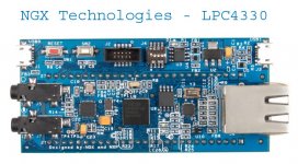
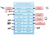
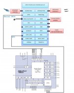
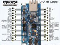
A possible DSP target would be the newest NXP LPC4330 featuring a Cortex-M4 enhanced by a Cortex-M0 servicing the Serial GPIO interrupt for generating the required I2S lanes. I just found the NGX Technologies LPC4330 Xplorer board, soon to be released. See attached pictures. Clearly, the J8 header is conveying SPI1 for the Codec control bus. Can somebody tell me if the J8 and J10 headers are conveying enough Serial GPIO lines for the Codec data bus (implementing four I2S-out lanes, one I2S-in lane, plus the associated bit clock and frame sync)?
Attachments
Last edited:
NXP Serial GPIO on LPC4330, from NXP website NXP’s New Dual-Core Cortex-M4 and M0 MCU Redefines Digital Signal Control :: NXP Semiconductors
NXP’s Serial GPIO, available for the first time on the LPC4000, allows a developer the flexibility to interface to any non-standard serial interface or to mimic multiple standard serial interfaces (such as I2S, TDM for multi-channel audio, I2C and more).
Question : is there Serial GPIO sample code available, for generating four I2S-out and one I2S-in, sharing a bit clock and a frame sync ?
Additional Serial GPIO info : watch this video : http://ics.nxp.com/support/training/sgpio.sct/
Last edited:
Pricey... 170$ for just a CPU is plain pricey...
From price point of view, Android device would be much better choice for the same price range. If you stick to some standart I/O bus (HDMI, USB), then you get hardware-independent solution, with Android as DSP and media player (touchscreen, WiFi, LAN, USB Host, memory). Add a squeezebox player app, and you're done implementing LAN DAC.
There is a GPU which could do the DSP processing just like a CUDA does...
Look again : the order I've made is about two LPC4330 Xplorer, two USB->JTAG converters, plus worldwide shipment.NXP LPC4330 is pricey, 170$ for just a CPU is plain pricey.
As developer, you only need one USB-JTAG converter during the whole project life. I ordered two of them in order to avoid an interruption in the development cycle, in case I commit a fatal hardware mistake. Same approach for the LPC4330 Xplorer : I ordered two of them, as a safety precaution.
Once the LPC4330 gets programmed, the micro-USB connectivity would be used (along with a small PC application possibly written using Visual Basic), for changing the crossovers parameters. If you are not a developer, you don't need the USB-JTAG converter. If you are not a developer, you only need one LPC4330 Xplorer.
The micro-USB connectivity can be used as power supply.
A standalone 3-way stereo crossover with S/PDIF input and analog input could be built using :
- one audio-PCB used as motherboard, hosting an audio-grade voltage regulator, a WM8580 Codec, and the audio connectivity
- one LPC4330 Xplorer carrierboard plugged on the motherboard using the 2 x 27 pin headers
Mouser is currently supplying the WM8580 in 250 qty for $7.74, delay 18 weeks.
A standalone 4-way stereo crossover with S/PDIF input and analog input could be built using :
- one audio-PCB used as motherboard, hosting an audio-grade voltage regulator, a WM8581 Codec, and the audio connectivity
- one LPC4330 Xplorer carrierboard plugged on the motherboard using the 2 x 27 pin headers
Mouser is currently supplying the WM8580 in 250 qty for $7.53, delay unspecified.
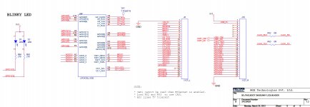
Ashwin Athani (Director, NGX Technologies Pvt. Ltd.) just emailed me the LPC4330 Xplorer pinout when used as carrierboard.
See the attached picture.
In his email, Ashwin Athani confirms that "it is possible to implement a 7.1 Audio using the LPC4330 Xplorer. In all it has about 14 SGPIO lines brought out to the header J8 and J10 together."
The audio-PCB would host a RC5 Infrared Remote Control Receiver, sending control data to the LPC4330 for the volume control. Such RC5 receiver is a 3 terminal device containing the photodiode, the filter and the demodulator, costing less than $1.
If we manage to produce the motherboard in batches of 250 units, the $170 price tag you are referring is the price you would pay as final customer, including shipment and tax, for a standalone 4-way stereo crossover with S/PDIF input and analog input, with support for a RC5 volume control. Don't know yet what kind of enclosure is possible considering such price.
Okay, with a WM8580 or WM8581 onboard, we cannot say this is high-end. I agree there is no alchemy in there. Distorsion and noise will be about -90 dB. For me, this is a perfectly valid starting point. There is no ASRC onboard which means that the Codec would run at a 44.1 KHz sample rate when connected on daddy's Compact Disc Player (or PC). The Codec would run at a 48 kHz sample rate when connected on a DVD or a Blu-ray. If you own vinyles, if you ripped them using the 24bit/96kHz standard, or if you own genuine 24bit/96kHz HDTracks, there is the possibility to buy a 2496 USB-SPDIF converter and hook it on your MAC or PC, for sending "bit exact" 24bit/96kHz S/PDIF audio to the crossover.
Attachments
Last edited:
I forgot to mention that on NGX website, the LPC4330 Xplorer status just changed from "don't exist in desired quantity in our stock" to "available". Anybody can now place an order, and expect a delivery within days instead of weeks.
Let's start designing the WM8580/WM8581 audio motherboard, hosting an audio-grade voltage regulator, a WM8580 Codec, and the audio connectivity ! Shall we add opamps at the analog-ins and analog-outs ? What PCB design software should be used ?
The WM8581 datasheet is here : http://www.wolfsonmicro.com/documents/uploads/data_sheets/en/WM8581.pdf
Found this document about no opamps needed at the analog-outs : http://www.wolfsonmicro.com/documents/uploads/flyers/en/WM8522-8501.pdf
Last edited:
I considered and rejected the Wolfson multichannel codecs as the Cirrus parts use minimum phase filters with wider transition bands, offer a bit more performance margin to work with, drive lower impedance loads, and are more readily available in DIY quantities. The only real drawback I saw is Wolfson specs jitter on the recovered SPDIF clock whereas Cirrus does not.
You might want to run a similar analysis---the CS42526 is a reasonable starting point.
You might want to run a similar analysis---the CS42526 is a reasonable starting point.
Last edited:
There can be two different audio mainboards : one featuring a WM8580/WM8581, and one featuring a CS42516/CS42526/CS42518/CS42528. The subjective listening results will vary in function of the Codec model, and in function of the input that's used (S/PDIF-in or Analog-in). In such context, the CS42526 is a reasonable starting point too. Rejecting a Codec family basing on figures on paper, is less reasonable. You need to give a chance to everybody, yourself included. You may want an audio mainboard featuring a Wolfson S/PDIF receiver with ultimate jitter rejection, no Analog-ins, and a set of high quality stereo DACS, a set of audiophile opamps as low-pass filters, a set of digitally controlled analog volume controllers, and a set of balanced line drivers as outputs. Having done this, you then realize you would be better with keeping the balanced signal at 0 dB for getting a better noise immunity in the transport to your poweramps. Which means that you need to place the digitally controlled volumes at the inputs of your poweramps. Then comes the question of ground loops. You may want to install isolation barriers. It is a never ending story. All the bells and whistles will come in due time, after some trivial debunking job gets finalized like learning how to program and debug the LPC4330 chip.I considered and rejected the Wolfson multichannel codecs as the Cirrus parts use minimum phase filters with wider transition bands, offer a bit more performance margin to work with, drive lower impedance loads, and are more readily available in DIY quantities. The only real drawback I saw is Wolfson specs jitter on the recovered SPDIF clock whereas Cirrus does not. You might want to run a similar analysis---the CS42526 is a reasonable starting point.
Last edited:
sorry for jumping into this discussion lately. i have not gone thro all the posts yet.
@steph_tsf: LPC4330 Xplorer board looks good for i2s connectivity point of view, but will it be capable of doing all the DSP work!? this board is having a sd card slot, so instead of supplying audio data from ext. codec, we can just read the data from card and do the xover processing on it directly. right?
i hope my question makes sense!!
Not all of us have the time and resources to DIY multiple solutions to the same problem. Sometimes one has to pick and choose.Rejecting a codec family basing on figures on paper, is less reasonable. You need to give a chance to everybody, yourself included.
Right ! You may store a few soundtracks on the SDCARD, and ask the LPC4330-Xplorer to process them realtime in digital domain. This way you can demo the stereo 4-channel crossover without needing an external audio source.LPC4330 Xplorer board looks good for i2s connectivity point of view, but will it be capable of doing all the DSP work!? this board is having a sd card slot, so instead of supplying audio data from ext. codec, we can just read the data from card and do the xover processing on it directly.
Speaking about 8-channel audio demos, you can generate multichannel dynamic sound effects like smoothly "moving" the sound from one output to the other, surprising the audience, attracting the audience. You may embed this into public transportation systems, shop & bar entrances, exhibition booths, vending machines, casino machines.
Don't worry about the audio DSP capabilities of the LPC4330. Say the Cortex-M0 is entirely busy servicing the Serial GPIO. The Cortex-M4 remains thus available for general housekeeping and audio DSP. Say the audio DSP job represents 75% of the Cortex-M4 workload. Say there are 12 Cortex-M4 instructions needed for executing a BiQuad IIR. Say the CPU clock is 100 MHz. Say the audio sampling frequency is 48 kHz. You thus can execute 130 BiQuad IIRs. Say there are 8 audio channels. Each audio channel can thus get processed by 16 IIR BiQuads in series.
There is one area where the LPC4330-Xplorer board may be lagging : RAM capacity. In this particular case, plugging a SDCARD into the system, you can use it as slow RAM, operating at the audio sampling frequency. If, for example, you need to introduce delays in the audio rendering, you would read the audio soundtrack in the SDCARD, using eight different pointers. This way you get all the time shifts you want.
Last edited:
This is what you can achieve on a LPC4330 provided there is no bloat caused by an OS like Linux or Android. The above figures are only valid in a "bare metal" programming style structured as a main_loop (where all the background tasks get explicitely scanned) plus a proper 48 kHz interrupt (context save, all the audio DSP on a sample-by-sample basis, context restore). Adding a SPI communication for sending control data to the Codec will cause an extra interrupt, to be carefully managed for not interfering with the 48 kHz interrupt. A possibility is to manage such SPI, not using a hardware SPI, but using a software SPI (bit-banging) operating at 48 kHz, programmed within the audio DSP interrupt. Adding a RC5 remote control decoder will cause an extra interrupt, to be carefully managed. Adding some USB-audio capability will decrease the Cortex-M4 available DSP time. Adding the SDCARD as bulk storage will cause some overheads, decreasing the Cortex-M4 available DSP time.
Last edited:
... the Cirrus parts use minimum phase filters with wider transition bands...
The Cirrus part you quoted explicitly says its linear phase - p74, para 8.2 of the datasheet.
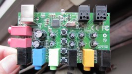
I'm still convinced that attaching a SWEEX SC016 on the USB-host of a PIC32 carrierboard or ARM Cortex-M3/M4 carrierboard is an interesting way to build an Open Source DSP XO featuring the S/PDIF-in and the analog stereo line-in. Not high-end, good enough for experiments.
How much for the SWEEX SC016 nowadays ?
Less than $25 on eBay, excluding shipment.
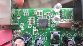
Absolutely required for such job, is the CM6206 datasheet from Cmedia.
Website here : C-Media Electronics, Inc.
Where can we find such datasheet ?
What carrierboards are available, equipped with a USB-host directly connecting on a 32-bit processor having DSP aptitudes ?
- STM32F4 discovery at $17 (Mouser USA)
- Embedded Artists LPC1769 LPCXpresso (need to solder a USB connector on J6-36 and J6-37) at $33 (Mouser USA)
- PIC32 USB Starter Kit II (DM320003-2) at $55 (Microchip Direct)
- NGX LPC4330-Xplorer at $57 (NGX technologies website)
The carrierboard budgetary price is thus from $17 to $57, depending on the model, excluding shipment.
The NGX LPC4330-Xplorer at $57 currently is the sole and only carrierboard that could be reused for building a high-end stereo 4-way crossover, once installed on a dedicated audio motherboard featuring a better S/PDIF receiver and better DACs than inside the CM6206 chip. The reason is the LPC4330 Serial GPIO and Cortex-M0 coprocessor, able to deliver five I2S lanes (one as input, four as outputs).
If you intend developing software for the NGX LPC4330-Xplorer, you need an external USB->SWD (Cortex Debug) solution. The obvious solution is to use the ULINK2 (less than $35 on eBay USA) or the Embedded Artists LPC1227 LPCXpresso LPC-LINK (about $40). This is what NGX developers used for debugging the demo software accompanying the NGX LPC4330-Xplorer. Plus the required 10 wire cable terminated by the 2x5 pin female mini-header. Which is going to be standard for all new Cortex-M4 boards. The Keil µVision and the Code Red Suite 4 are essentially free of charge, when code size is less than 32K.
How much for the SWEEX SC016 nowadays ?
Less than $25 on eBay, excluding shipment.
Absolutely required for such job, is the CM6206 datasheet from Cmedia.
Website here : C-Media Electronics, Inc.
Where can we find such datasheet ?
What carrierboards are available, equipped with a USB-host directly connecting on a 32-bit processor having DSP aptitudes ?
- STM32F4 discovery at $17 (Mouser USA)
- Embedded Artists LPC1769 LPCXpresso (need to solder a USB connector on J6-36 and J6-37) at $33 (Mouser USA)
- PIC32 USB Starter Kit II (DM320003-2) at $55 (Microchip Direct)
- NGX LPC4330-Xplorer at $57 (NGX technologies website)
The carrierboard budgetary price is thus from $17 to $57, depending on the model, excluding shipment.
The NGX LPC4330-Xplorer at $57 currently is the sole and only carrierboard that could be reused for building a high-end stereo 4-way crossover, once installed on a dedicated audio motherboard featuring a better S/PDIF receiver and better DACs than inside the CM6206 chip. The reason is the LPC4330 Serial GPIO and Cortex-M0 coprocessor, able to deliver five I2S lanes (one as input, four as outputs).
If you intend developing software for the NGX LPC4330-Xplorer, you need an external USB->SWD (Cortex Debug) solution. The obvious solution is to use the ULINK2 (less than $35 on eBay USA) or the Embedded Artists LPC1227 LPCXpresso LPC-LINK (about $40). This is what NGX developers used for debugging the demo software accompanying the NGX LPC4330-Xplorer. Plus the required 10 wire cable terminated by the 2x5 pin female mini-header. Which is going to be standard for all new Cortex-M4 boards. The Keil µVision and the Code Red Suite 4 are essentially free of charge, when code size is less than 32K.
Attachments
Last edited:
- Status
- This old topic is closed. If you want to reopen this topic, contact a moderator using the "Report Post" button.
- Home
- Source & Line
- Digital Line Level
- Open Source DSP XOs