What you just described is the "Lipshitz-Vanderkooy delay compensated crossover" presented at the 69th Convention 1981 May 12-15 Los Angeles. The exact title of the AES preprint was "A Family of Linear-Phase Crossover Networks of High Slope Derived by Time Delay".Here's a 4th order MFB lowpass that I'd like to have as a digital filter. But here you'll notice there's a delay line for the HP rather than the traditional two opamp Sallen-Key. With the delay line matching the filter's asymptotic group delay, the HP subtracted output looks like the last plot.
In your example you have used the double Butterworth 2nd order (4th order in total) as lowpass kernel, as recommended by Lipshitz-Vanderkooy 1) for delivering a moderate time smear, 2) for maximizing the highpass selectivity, 3) for suppressing the relative phase shifts in the transition band.
Your lowpass filter uses the "MFB" architecture, which is an acronym for "Multiple FeedBack", generally preferred over the Sallen-Key architecture. The MFB" architecture helps keeping the noise floor down and helps keeping the input capacitance modulation down.
If you use a 8th order Bessel as lowpass kernel, you get no time smear at all, the lowpass selectivity gets better than the double Butterworth, but you slightly degrade the highpass selectivity and you introduce a small amount of relative phase shift in the transition band.
What Stanley P. Lipshitz and John Vanderkooy have not made clear in their publication, is that you can increase the highpass selectivity in the transition band by slightly overisizing the delay. Have you tried this yet ?
What I very much like in your approach is the idea of synthesizing the same lowpass kernel using a FIR, by duplicating the resulting impulse response untill -60 dB. Practically, in the real world, we don't care if there are wiggles -40 dB down in the lowpass function. It is very encouraging to see those interesting results with a FIR as short as 32-tap. Have you tried with a 8th-order lowpass Bessel, using a 64-tap FIR ?
When implementing such crossover in the real world, make sure that the acoustic centres of the woofer and the tweeter get properly time-aligned. If the woofer and the tweeter are flush-mounted (as it is the case mostly), the woofer appears as delayed. As consequence, you need a second delay line in the system, that you put after the highpass, for slightly delaying the tweeter signal.
As soon as you depart from the Linkwitz-Riley (double 2nd order Butterworth) providing a zero relative phase shift in the transition band, you need to use the symetric MTM (Woofer-Tweeter-Woofer) arrangement for getting a decent omnidirectional, smooth polar radiation pattern.
Last edited:
What you just described is the "Lipshitz-Vanderkooy delay compensated crossover" presented at the 69th Convention 1981 May 12-15 Los Angeles. The exact title of the AES preprint was "A Family of Linear-Phase Crossover Networks of High Slope Derived by Time Delay".
Cool
 Nice to know I'm not totally breaking new ground here.
In your example you have used the double Butterworth 2nd order (4th order in total) as lowpass kernel, as recommended by Lipshitz-Vanderkooy 1) for delivering a moderate time smear, 2) for maximizing the highpass selectivity, 3) for suppressing the relative phase shifts in the transition band.
Your lowpass filter uses the "MFB" architecture, which is an acronym for "Multiple FeedBack", generally preferred over the Sallen-Key architecture. The MFB" architecture helps keeping the noise floor down and helps keeping the input capacitance modulation down.
Yes - not only the input capacitance modulation but also any other common-mode non-linearities introduced by the opamp LTP stage, which turn out not to be suppressed by NFB. Also it gives flexibility to add in baffle step correction if required (not shown here) with just a couple of extra components.
If you use a 8th order Bessel as lowpass kernel, you get no time smear at all, the lowpass selectivity gets better than the double Butterworth, but you slightly degrade the highpass selectivity and you introduce a small amount of relative phase shift in the transition band.
I'll have to turn up Williams' book to get the design parameters I think. Something to play with for the future.
What Stanley P. Lipshitz and John Vanderkooy have not made clear in their publication, is that you can increase the highpass selectivity in the transition band by slightly overisizing the delay. Have you tried this yet ?
No - I was very happy with the response I got here - but if you'd like I'll email you the LTSpice files and you can have a play
What I very much like in your approach is the idea of synthesizing the same lowpass kernel using a FIR, by duplicating the resulting impulse response untill -60 dB. Practically, in the real world, we don't care if there are wiggles -40 dB down in the lowpass function. It is very encouraging to see those interesting results with a FIR as short as 32-tap. Have you tried with a 8th-order lowpass Bessel, using a 64-tap FIR ?
No - not yet. But you've given me pleasant food for thought - if the Williams book does have the Bessel coefficients, I'd like to try it. Thanks for your supportive comments
Hello abraxalito, here attached in a .zip are a few LTspiceIV Lipshitz-Vanderkooy simulations. As you will see, to our great sorrow, tweaking the substractor delay when you base on a high order Bessel lowpass kernel doesn't increase the highpass selectivity in the transition band. On the other hand, tweaking the substractor delay when you base on a high order Butterworth lowpass kernel (a true Butterworth, not the Linkwitz-Riley variant) can significantly increase the highpass selectivity in the transition band. By plotting the (V_hp/V_lp) phase graph, you can keep an eye on the relative phase shifts in the transition band, as shown in the .doc example.
Attachments
Last edited:
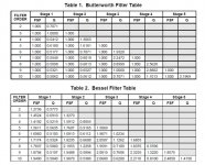
Hello abraxalito, here attached are the required tables for designing high order analog Butterworth and high order analog Bessel filters using cascaded 1st and 2nd order cells. From T.I. Application Report SLOA049B - September 2002 "Active Low-Pass Filter Design" by Jim Karki.
Attachments
Last edited:
Hello Brunos, indeed it is tempting to have the Actel smartfusion Cortex-M3 + FPGA providing one I2S as input and four I2S as output, all operating on 24 bit 96 kHz, plus one SPI as general control at 96 kbit/s and a few chip_select. Is it feasible on the Actel A2F-EVAL-KIT at 99$, only using the FPGA and the SPI-Flash ? Shall we connect on the Mixed Signal Header ?Another interesting technology which is coming up is the mixed ARM/FPGA processors such as Xilinx Zynq 7000, which does have an open source environment. I personally find FPGA programming quite difficult, but last year I have tried (for work) the Actel smartfusion, which is a cortex M3+FPGA. You program it just like any other ARM, say with Keil, but with the possibility of adding custom ports/DSP instructions etc. The design tool then generates the c drivers automatically, and you just call the functions from your ARM code. For an open platform and FPGA does offer some advantages, and they have really come down in prices in the last few years (the Actel dev board was 90$).
Currently I'm bored with the PIC32MX2 and STM32 F4 (both provide two I2S - that's not enough), me needing to dig into the configuration registers, me needing to learn their development environments, etc.
I'm doing all this, hoping that in the next few months, there will be new Microchip PIC32 variants featuring four I2S, or new ARM Cortex-M0+ or ARM Cortex-M4 featuring four I2S.
Four I2S on Cortex-M4 are already feasible using the NXP LPC43xx (Cortex-M4 plus Cortex-M0 as coprocessor), but the programmable serial engine is hard to configure and the resulting high interrupt rate consumes the built-in Cortex-M0. Currently, the NXP LPC43xx is still needing an external Flash chip. This currently makes the NXP LPC43xx based solution a cumbersome solution, miles away from a two-chip solution (CPU + Codec).
A few days ago, after having fiddled with all those microcontrollers, I concluded that the learning curve would not be steeper, using the Actel smartfusion. Like you said, the FPGA brings flexibility. Using the Actel smartfusion FPGA, is it feasible to interface the codec using TDM or TDMCA (this is a kind of I2S containing 8 channels instead of 2 channels) ?
Consider a dedicated PCB, without built-in debug circuitry, only containing the voltage regulator, reset circuit, quartz, serial Flash, FPGA, expansion connector and USB-device connector. What would be the current drain with the Cortex-M3 multiplier executing 100 32x32+64=64 multiply-accumulate each 10 µs ? What would be the BOM cost ? What external debug probe to use ? Will you sketch something ?
Last edited:
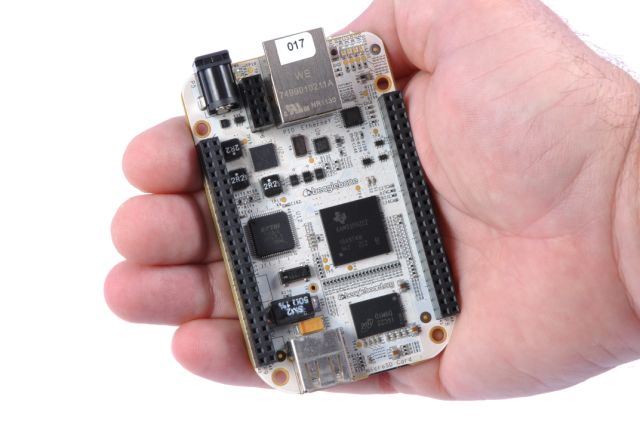
has anyone seen the beaglebone ? Sounds like a good starting point.
BeagleBoard.org - bone
89 bucks gets you
BeagleBoard.org - bone
89 bucks gets you
>700-MHz superscalar
ARM
Cortex™-A8
• 256-MB DDR2 RAM
• 1-port USB 2.0 host
• Integrated 10/100 Ethernet
• microSD slot and 2-GB
microSD card with
validation and
demonstration image
from the Angstrom
Distribution
• USB 2.0 fl exible device
port with ability to supply power
• On-board USB-to-serial/JTAG over shared USB
device port
• 3.3-V 2× 46-pin peripheral with multiplexed LCD
signals and battery-control expansion headers
• Board size: 3.4” × 2.1”
has anyone seen the beaglebone ?
Its the real version of the very much still-virtual Raspberry Pi
has anyone seen the beaglebone ? Sounds like a good starting point.
I have one, will do some performance testing in the next few weeks to see what its good for. I got impatient waiting for RPi and ordered ...
I have one, will do some performance testing in the next few weeks to see what its good for. I got impatient waiting for RPi and ordered ...
According to the specs for the AM3358 - ARM Cortex-A8 used on the begalbone only has 2 McASP ports so is this a limitation ?
Edit: I found out that it is the McBSP that is limited. Although both can do I2S the McASP is buffered and has four serializers each of which can do I2S.
Last edited:
While it's possible and perhaps with a multichannel I2S FIFO you could clean up the clocks etc. I was really hoping that with a multichannel usb to i2s device it wouldn't need onboard i2s. I am waiting to see what comes of the recent XMOS multichannel usb development kits. Certainly it adds expense to the setup and commits you to building a multichannel DAC as well.
My first project planned for the board is to build it into a headphone dac/amp (for playback from NAS/DAC register control/UI display) and at same time use it to benchmark some XO/DRC on it before I decide direction of my main system. I've used linux before but embedded development is a bit of a new thing for me so I chose an easier project to start on.
My first project planned for the board is to build it into a headphone dac/amp (for playback from NAS/DAC register control/UI display) and at same time use it to benchmark some XO/DRC on it before I decide direction of my main system. I've used linux before but embedded development is a bit of a new thing for me so I chose an easier project to start on.
While it's possible and perhaps with a multichannel I2S FIFO you could clean up the clocks etc. I was really hoping that with a multichannel usb to i2s device it wouldn't need onboard i2s. I am waiting to see what comes of the recent XMOS multichannel usb development kits. Certainly it adds expense to the setup and commits you to building a multichannel DAC as well.
My first project planned for the board is to build it into a headphone dac/amp (for playback from NAS/DAC register control/UI display) and at same time use it to benchmark some XO/DRC on it before I decide direction of my main system. I've used linux before but embedded development is a bit of a new thing for me so I chose an easier project to start on.
I assume it has a linux kernal running on the board. What is the overhead of this when using the board for DSP apps ? Can you access the hardware directly or do you have to go through the operating system ?
Also I noted the ARM3358 on the begalbone does not do floating point whereas the OMAP3530 used on the begalboard does,
Last edited:
According to the specs for the AM3358 - ARM Cortex-A8 used on the begalbone only has 2 McASP ports so is this a limitation ?
Edit: I found out that it is the McBSP that is limited. Although both can do I2S the McASP is buffered and has four serializers each of which can do I2S.
Actually I stand corrected. It is the McASP which is the more basic serial port compared to the buffered version McBSP which is featured on the beagleboard. Both are capable of processing audio.
How about the CuBox or Raspberry Pi platforms? One could develop the DSP software for Linux or Android, but one would also need an external multi-channel USB interface.
I already plan to use the CuBox for two channel Digital Room Correction, and as the primary media server for my TV.
I already plan to use the CuBox for two channel Digital Room Correction, and as the primary media server for my TV.
New low cost chineese androphones have arrived, like the ZOPO ZP100. They are all based on the latest Mediatek MT6575 SoC. This is a Cortex-A9 CPU (single core) clocked at 1 GHz plus a PowerVR SGX GPU. It runs Android 4.0.
It is tempting to have the Open Source DSP XO running Android 4.0, basing on a minimalist MT6575 mainboard. But wait a minute : how many I2S or TDM lines get delivered by the MT6575 SoC ?
What if hooking an off-the-shelf USB 5.1 audio adapter, writing the required driver for Android 4.0 ? This way, any Android 4.0 device equipped with a USB 2.0 host would act as Open Source DSP XO.
I don't know of any good quality USB 5.1 adapter for a reasonable price. The exa u2i doesn't allow any possibility for linux drivers so its crossed off straight up. Hopefully the new xmos multichannel dev board starts a few projects in this direction!
EDIT: I am assuming you mean usb -> i2s multichannel.
EDIT: I am assuming you mean usb -> i2s multichannel.
I believe this would be a very smart option. Also, if the device supports HDMI, is there a way to connect an external HDMI audio interface to support up to eight channels?This way, any Android 4.0 device equipped with a USB 2.0 host would act as Open Source DSP XO.
The way things are going, I envision our phones becoming replacements for notebooks and desktop computers. People simply plug the phone into a workstation for a monitor / keyboard interface. Ubuntu for Android is a prime example. Fully replacing a Desktop computer with a phone is probably a few years down the road, but it's not that far off.
Why not do the same for a DSP crossover? Utilize the power of the phones we carry around in our pockets. Interface with either a HDMI or USB -> i2s multichannel.... Or Just use something like the Raspberry pi or Cubox to get started.
What about the audio quality when multichannel audio needs go over USB 2.0, then needs to be splitted into four I2S lanes or one 8-channel TDM lane ?Utilize the power of the phones we carry around in our pockets. Interface with either a HDMI or USB -> i2s multichannel.... Or Just use something like the Raspberry pi or Cubox to get started.
And the audio input ? Need an S/PDIF input (with or without a sample rate converter), or a high quality stereo ADC.
Where is the master clock ? How to avoid jitter ? Are there high quality USB 2.0 multichannel audio systems available, operating full duplex ?
Able to lock on the S/PDIF clock (and no jitter) when using the S/PDIF input, and able to become the master clock when using the stereo ADC input ?
Is there a low power (low EMI) XMOS chip doing all this straight from USB 2.0, delivering four I2S lanes or one 8-channel TDM lane ?
This is the mulitchannel xmos usb interface I referred to - USB Audio 2.0 Multichannel Reference Design | XMOS
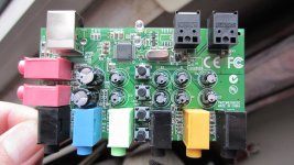
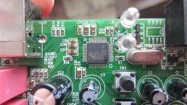
Looks like a joke, overkill. We don't need programmability here. Isn't there a 28-pin chip from Wolfson, T.I. or Cirrus specializing in "bit perfect USB 2.0 audio", a chip costing no more than 2 dollar, eating less than 20 milliwatt, delivering the required I2S and TDM lanes ? This is mass market. What kind of USB interfacing chip do we find in a 7.1 External USB Sound Card like the 7.1 External USB Sound Card - SC016 ? Reaching some "bit perfect" quality as advertized by XMOS doesn't justify a 50 x silicon cost increase.This is the mulitchannel xmos usb interface I referred to.
the 48-pin SWEEX SC016 chip reads :
CM6206
MPR8K
UYG1AMD-GS
0932
It is 48-pin because it also contains all the ADCs, DACs and SPDIF-in and SPDIF-out.
This is the sole and only chip in the SWEEX SC16 box.
Attachments
Last edited:
- Status
- This old topic is closed. If you want to reopen this topic, contact a moderator using the "Report Post" button.
- Home
- Source & Line
- Digital Line Level
- Open Source DSP XOs