Most chips run on a unipolar 5 V supply, making 0 dBFS measure at 1.8 Vrms. That should be plenty compared to the line level standard of 0.3 Vrms.Vout DACs are normally already at 2Vrms out.
> Is SEN your current ultimate sounding I/V or It wins because of simplicity
It is what I shall be using myself.
I don't use words like best or ultimate. Else I can stop.
Patrick
good to hear that
would you please tell us what type I/V you were using before SEN
I suggest that you are doing with pcm1704
")
No you can't use ground referenced supplies. It helps to think about capacitors as short circuits for AC then you will see that the drains of the fets (in the complimentary version) will move around with the superimposition of the voltage across the I/V resistor.
I don't like it either since any capacitance from either "leg" of the supply to ground will be charged by the voltage at the output of the I/V.
But its performance is so superb for such a simple circuit that I wouldn't hold that against it.
I don't like it either since any capacitance from either "leg" of the supply to ground will be charged by the voltage at the output of the I/V.
But its performance is so superb for such a simple circuit that I wouldn't hold that against it.
The floating supply does not float more than the output across R_iv.
So if you are not afraid of twisted wires at the output, you should not be afraid of any capacitance of the supply lines to Gnd.
In the test PCB we measured at Jan Didden's, we did not paid any attention to wiring and have them all over the place.
Yet the performance is there for all to see.
Patrick
If you don't like using floating supplies (I use them for circlotrons all the time) and insists on using fixed rails,
you can build the CEN Current Mirror circuit, with 10 transistors in total, higher noise and distortions.
Easy enough to modify my published PCB layout and make one yourself.
As said, Joachim's idea. So no PCBs from us for the CEN CM.
Patrick
you can build the CEN Current Mirror circuit, with 10 transistors in total, higher noise and distortions.
Easy enough to modify my published PCB layout and make one yourself.
As said, Joachim's idea. So no PCBs from us for the CEN CM.
Patrick
I showed a mirror with approximately the same amount of distortion as your circuits. The noise issue can be solved too with cascoding but then it is not simple any more.
I agree that a floating supply is not a problem to make. The easiest are buffered batteries or accumulators.
Somewhere in my files i have a design for a floating low noise supply that can be fed by a conventional mains transformer. When i can dig it up i will publish it if you like.
I agree that a floating supply is not a problem to make. The easiest are buffered batteries or accumulators.
Somewhere in my files i have a design for a floating low noise supply that can be fed by a conventional mains transformer. When i can dig it up i will publish it if you like.
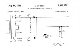
For the basic principle something as old as me.
Or using a few more parts.
Attachments
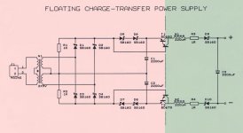
Interesting.Or using a few more parts.
The circuit on the left would not be covered by U.S. Patent 2,895,059 because it doesn't have the dummy load and does not use the center tap as ground. However, the circuit on the left is the one that I would intuitively build.
The circuit on the right does indeed look like an actively regulated version of 2,895,059 because there appears to be a dummy load (active, at that) and ground is taken from the center tap like in the patent. ... EDIT: Oops, that's not a dummy load. The circuit on the right is also not similar to the patent mentioned above.
Both examples would have leakage current to ground which patent 2,895,059 minimizes with its dummy load.
Last edited:
- Home
- Source & Line
- Digital Line Level
- Zen -> Cen -> Sen, evolution of a minimalistic IV Converter